


32
13
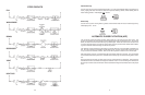
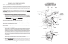
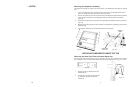
SECTION THREE
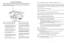
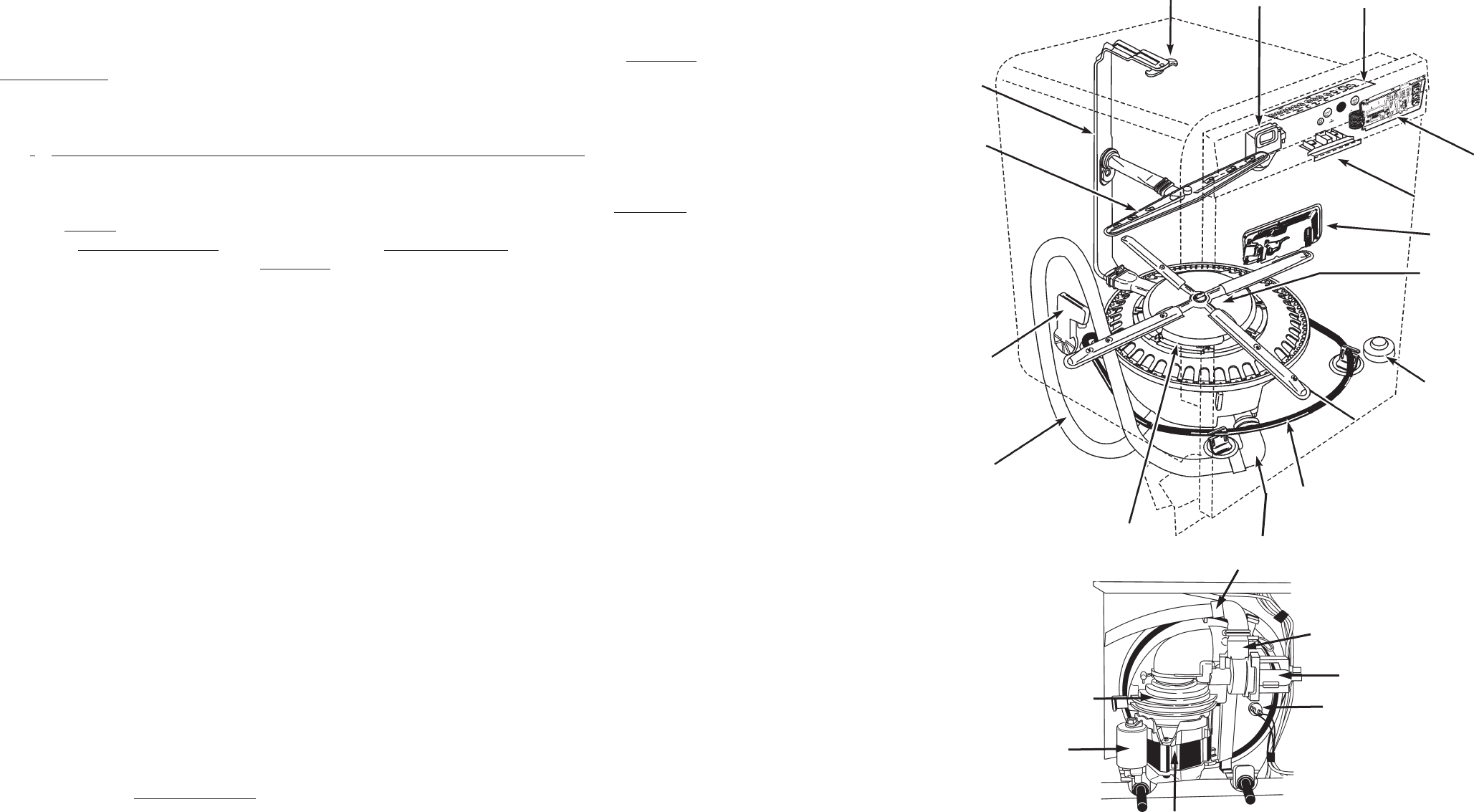
COMPONENT ACCESS
COMPONENT LOCATION
Inner Feed Tube
Middle Spray
Arm
Water Inlet
Drain Tube
Heating
Element
Float
Door Latch Assembly
Electronic
Control Board
(Interconnect
Board Underneath)
Active
Vent
Lower Spray
Arm
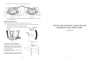
Sump and Motor
Assembly
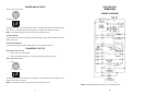
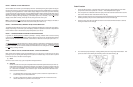
Upper
Spray
Arm
Dispenser
Assembly
Control
Panel
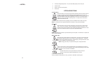
Check Valve
(in drain tube)
Accumulator
Soil Sensor
Pressure Switch
Drain Pump Motor
Thermistor
Run Capacitor
Wash Pump Motor
Wash Pump
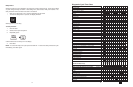
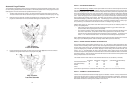
COMMON CYCLE TIME CHART NOTES
NOTE 1 – CYCLE MODIFICATIONS BASED ON SENSOR INPUTS
The control monitors food soil and temperature sensors during the first four intervals of the cycle
(intervals 45-42) to determine what sensor based cycle modifications are appropriate. The modifica-
tions made to the cycle depend on the cycle and options selected as well as the sensor inputs. Note
the interval skip arrows and thermal hold temperature changes on the time chart for each version of
the cycle.
In addition to being able to modify the cycle itself based on soil sensor input, the APF (
Automatic
Purge Filtration) wash system allows the control to continuously filter and flush food soil out of the
pump during “APF enabled” intervals scattered throughout each cycle and do it without interrupting
the cycle (see note 2 on APF).
(a
) Anti-Bacteria/Cookware, Pots & Pans/Heavy, Normal, and China Cycles
The control assumes that the worst case cycle (the high soil version) is going to be required
until the true soil level is determined. The soil level is determined by counting the number of
pressure switch (soil sensor) trips that occur in the first APF interval of the cycle (
interval 42).
If
no trips are detected in interval 42, the control modifies the remainder of the cycle to match
the
light soil/non-sensor version of the cycle. If one or more trips are detected in interval 42,
the control continues with the
heavy soil version of the cycle.
Note: Energy Star models have a different light soil/non-sensor version of the Normal cycle than
other models (see Model Specifics table to identify Energy Star models).
Note: Models without pressure switches (soil sensors) never get sensor trips and thus always default
to the light/non-sensor version of the cycle and never execute APF purges. (See Model Specific
Tables to identify models without pressure switches).
Note: The Power Scour/High Temp Scrub option can override or alter the soil-based cycle modifica-
tions (see note 14).
(b) Time Saver/Quick CleanUp Cycles
The control does NOT modify the Quick CleanUp/Time Saver cycle based on soil level. In-
stead, it modifies the cycle based on incoming water temperature detected during the first fill
interval of the cycle (interval 45). The control assumes the worst case cycle (Cool First Fill
version) will be required until the end of interval 42. At the end of interval 42, it modifies the
remainder of the cycle based on the inlet water temperature it actually detected in the first fill.
If the water was more than 135° F/57° C it changes to the “Hot First Fill” version of the cycle. If
the water was less than 135° F, it will continue with the “Cool First Fill” version of the cycle. The
“Cool First Fill” version of the cycle basically contains an extra drain and fill prior to the main
wash to increase the initial water temperature for the main wash and reduce the time needed
to heat the water.
Like other cycles, the Quick CleanUp/Time Saver cycle does allow APF purges to occur (in
APF intervals) if pressure switch trips occur, but cycle timing is not modified.
(c) Rinse Only/Quick Rinse Cycles
The control
does NOT modify the Rinse Only/Quick Rinse cycle based on sensor inputs. Like
other cycles, it does allow APF purges to occur (in APF intervals) if pressure switch trips occur
but the Rinse Only/Quick Rinse cycle timing itself is not modified based on any sensor inputs.