


7
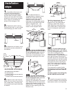
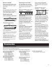
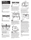
15. Check that the front
panel is parallel with the cabinet
front when the screen is pushed
in. Slide glass screen forward.
Tighten mounting bracket screws
so that vent hood is secured to
cabinet.
19. Turn power supply on.
Slide glass screen forward. Check
operation of vent hood fan and
light. Close glass screen.
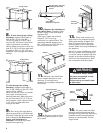
16. Align the hood front
panel with the cabinet: Slide
glass screen forward. Locate two
screws on each side and turn
counterclockwise to loosen
screws. Adjust front of vent
vertically [3/8" (9.5 mm) up or
down] or horizontally [3/4"
(19 mm) front to back] until front
is flush with cabinet. Tighten
screws. Do Not adjust more than
dimensions given.
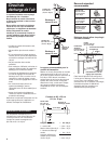
18. For vented installations:
Replace metal filters. Connect the
vent system to the hood vent
opening. Seal connection with
duct tape.
For non-vented (recirculating)
installations: Connect the vent
system to the hood vent opening.
Seal connection with duct tape.
Follow instructions included with
Kit No. 883140.
17. Connect the white wire of
the power supply cable to the
white wire in the hood with a
twist-on connector. Connect the
black wire of the power supply
cable to the black wire in the
hood with a twist-on connector.
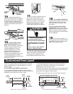
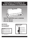
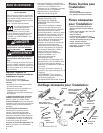
The front panel of the vent hood can be removed
and a customized front panel added for a more
blended look.
For the KWVU and YKWVU model series:
It is recommended that a cabinet maker cut the
customized front panel because of the precise cuts
needed for the electronic control panel.
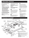
1. Use the dimensions shown to cut front panel for
either a 30" (76.2 cm) or 36" (91.4 cm) front panel,
depending on size of vent hood.
2. Remove the three cross-recess screws located behind
the front trim panel in the glass screen frame. Remove
front panel from glass screen frame.
3. Pull control panel from the front of the trim panel.
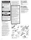
mounting
bracket
screw
flat-blade
screwdriver
adjustment
screws
Phillips
screwdriver
filter
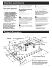
8-17/64" (21.0 cm)
panel front face
Section view of control panel cutout
Front view of control panel cutout
8-21/32" (22.0 cm)
2-3/8"
(6.0 cm)
2-9/16"
(6.5 cm)
11/32"
(8.7 mm)
14/32"
(11.1 mm)
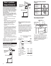
Customized front panel
7-31/64" (19.0 cm)
30" (76.2 cm) model: 29-7/8" (75.9 cm)
36" (91.4 cm) model: 35-7/8" (91.1 cm)
2-61/64"
(75.0 mm)
panel
front face
19/32"
(15.1 mm)
1-13/32"
(35.7 mm)
25/32"
(18.3 mm)
25/32"
(9.9 mm)
radius
panel
front face
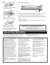
Electrical Shock Hazard
Disconnect power before
making electrical connections.
Connect ground wire to green
ground connector in terminal
box.
Failure to do so can result in
death or electrical shock.
WARNING
Connect the power supply ground
wire to the green, ground screw
inside the vent hood terminal
box. Replace terminal box cover.