


11
Make Gas Connection
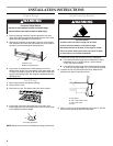
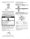
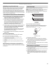
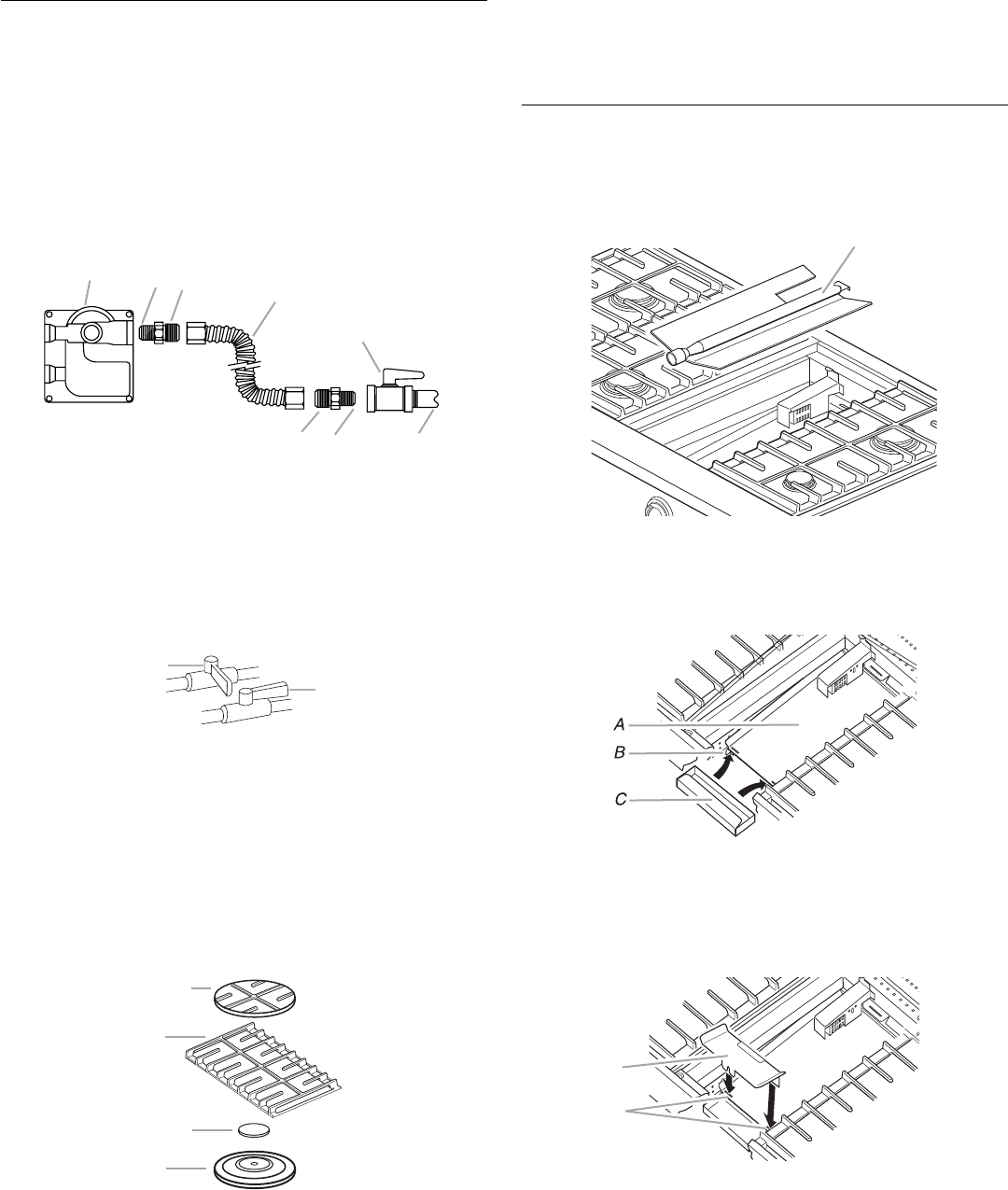
1. Assemble flexible connector from gas supply pipe to pressure
regulator located in the middle front of the range.
2. Apply pipe-joint compound made for use with LP gas to the
smaller thread ends of the flexible connector adapters (see B
and G in following illustration).
3. Attach one adapter to the gas pressure regulator and the
other adapter to the gas shutoff valve. Tighten both adapters.
4. Use a ¹⁵⁄₁₆" combination wrench and channel lock pliers to
attach the flexible connector to the adapters. Check that
connector is not kinked.
Complete Connection
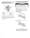
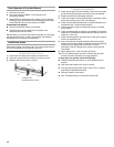
1. Open the manual shutoff valve in the gas supply line. The
valve is open when the handle is parallel to the gas pipe.
2. Test all connections by brushing on an approved
noncorrosive leak-detection solution. If bubbles appear, a
leak is indicated. Correct any leak found.
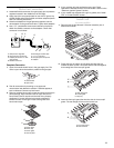
3. Remove cooktop burner caps, grates and simmer plate from
parts package. Align notches in burner caps with pins in
burner base. Burner caps should be level when properly
positioned. If burner caps are not properly positioned,
surface burners will not light. Place burner grates over
burners and caps.
4. If your cooktop only has surface burners, see “Check
Operation of Surface Burners, Grill and Griddle” section in the
“Electronic Ignition System” section.
5. If your model was shipped with a grill or griddle, see “Install
Grill” or “Install Griddle” section.
Install Grill
(on some models)
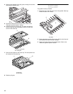
1. Remove twist tie and discard. Lift burner assembly out of
basin and set aside.
2. Place drip tray on bottom of grill basin and slide the tray
toward the back so that it is located side to side and against
the locating feet of the rear spill guard.
3. Insert the front spill guard feet into the slots in the rear spill
guard. The rear flange will rest on the burner box.
A.Gas pressure regulator
B.Use pipe-joint compound.
C.Adapter (must have ½" male
pipe thread)
D.Flexible connector
E.Manual gas shutoff valve
F. ½" or ¾" gas pipe
G.Use pipe-joint compound.
H.Adapter
A.Closed valve
B.Open valve
A.Burner base
B.Burner cap
C.Burner grate
D.Simmer plate
A
B
C
D
E
FG
H
A
B
A
B
C
D
A. Burner assembly
A.Rear spill guard
B.Locating feet
C.Drip tray
A.Front spill guard
B.Feet and slots
A
A
B