


23
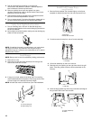
5. Apply masking tape to the end of a 7 mm nut driver to help
hold the gas orifice spud in the nut driver while changing it.
Insert nut driver into the gas opening and press down onto
the gas orifice spud and remove by turning the gas orifice
spud counterclockwise and lifting out. Set gas orifice spud
aside.
6. Replace with correct Natural gas orifice spud. See the
“Natural Gas Orifice Spud/Hood Chart.”
Use the following chart to find the exact orifice spud
placement.
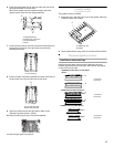
Natural Gas Orifice Spud/Hood Chart
7. Place LP gas orifice spuds in plastic parts bag for future use
and keep with package containing literature.
8. Replace the burner base using both screws.
9. Replace burner head and cap.
10. Repeat steps 2 through 9 for the remaining burners.
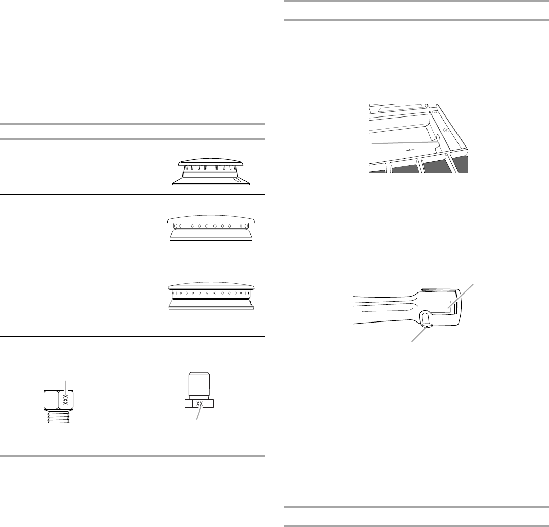
To Convert Grill Burner (on some models)
1. Remove grill grate, wave plate, flame spreader and burner
assembly. See “Install Grill Grease Trays” section for removal
instructions. Set parts aside.
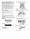
2. Use a ½" deep-well socket and remove the LP gas orifice
hood. Replace with correct grill Natural gas orifice hood. See
“Natural Gas Orifice Spud/Hood Chart.”
3. Turn Natural gas orifice hood down tightly onto orifice base.
4. Place LP gas orifice hoods in plastic parts bag for future use
and keep with package containing literature.
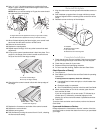
5. Before replacing the burner assembly, loosen the screw at the
front of the burner and rotate the shutter so that the opening
is ³⁄₈" (9.0 mm) wide.
6. Reinstall the burner assembly, flame spreader, wave plate,
and grill grate. See “Install Grill Grease Trays” section for
installation instructions.
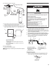
7. Open shutoff valve in the gas supply line. The valve is open
when the handle is parallel to the gas pipe.
REMEMBER: Once you have completed converting the grill,
test the range for leaks by brushing on an approved
noncorrosive leak-detection solution. Bubbles will show,
indicating a leak. Correct any leaks found.
8. Plug in range or reconnect power.
Complete Installation
1. Refer to the “Make Gas Connection” section for properly
connecting the range to the gas supply.
2. Refer to the “Electronic Ignition System” section for proper
burner ignition, operation, and burner flame adjustments.
IMPORTANT: You may have to adjust the “LO” setting for
each cooktop burner.
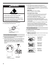
Checking for proper cooktop burner flame is very important.
The small inner cone should have a very distinct blue flame
¼" (0.64 cm) to ½" (1.3 cm) long. The outer cone is not as
distinct as the inner cone. LP gas flames have a slightly
yellow tip.
3. Refer to “Complete Installation” in the “Installation
Instructions” section of this manual to complete this
procedure.
Burner Rating Size Burner Style
5,000 BTU 1.01 mm Small burners
15,000 BTU 1.75 mm Medium burners
20,000 BTU 1.89 mm
0.69 mm
Large burner - main
Large burner - simmer
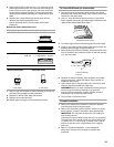
18,000 BTU 1.93 mm Grill burner
Burner orifice spud Grill orifice hood
A. Size stamp
A. Size stamp
A
A
A.Grill orifice hood location
A.Shutter opening
B.Screw
A
A
B