


16
Natural Gas Conversion
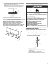
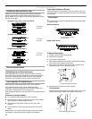
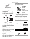
1. Turn manual shutoff valve to the closed position.
2. Unplug cooktop or disconnect power.
To Convert Gas Pressure Regulator
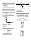
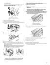
1. Remove the access cap by using a wrench, turning the
access cap counterclockwise.
2.
Remove spring retainer from the cap by pushing against the
flat side of the spring retainer. Look at the spring retainer to
locate the “LP” or “NAT” position. Turn over the spring retainer
so the “NAT” is showing on the bottom. Snap the spring
retainer back into the cap. Reinstall the cap onto the regulator.
3. Test the gas pressure regulator and gas supply line.
The regulator must be checked at a minimum 1" (2.5 cm)
water column above the set pressure. The inlet pressure to
the regulator should be as follows for operation and checking
the regulator setting:
Natural Gas:
Minimum pressure: 6" (15.2 cm) WCP
Maximum pressure: 14" (35.5 cm) WCP
Gas Supply Pressure Testing
Gas supply pressure for testing regulator must be at least
1" water column pressure above the manifold pressure
shown on the model/serial rating plate.
Line pressure testing above ½ psi gauge (14" WCP)
The cooktop and its individual shutoff valve must be
disconnected from the gas supply piping system during any
pressure testing of that system at test pressures in excess of
½ psi (3.5 kPa).
Line pressure testing at ½ psi gauge (14" WCP) or lower
The cooktop must be isolated from the gas supply piping
system by closing its individual manual shutoff valve during
any pressure testing of the gas supply piping system at test
pressures equal to or less than ½ psi (3.5 kPa).
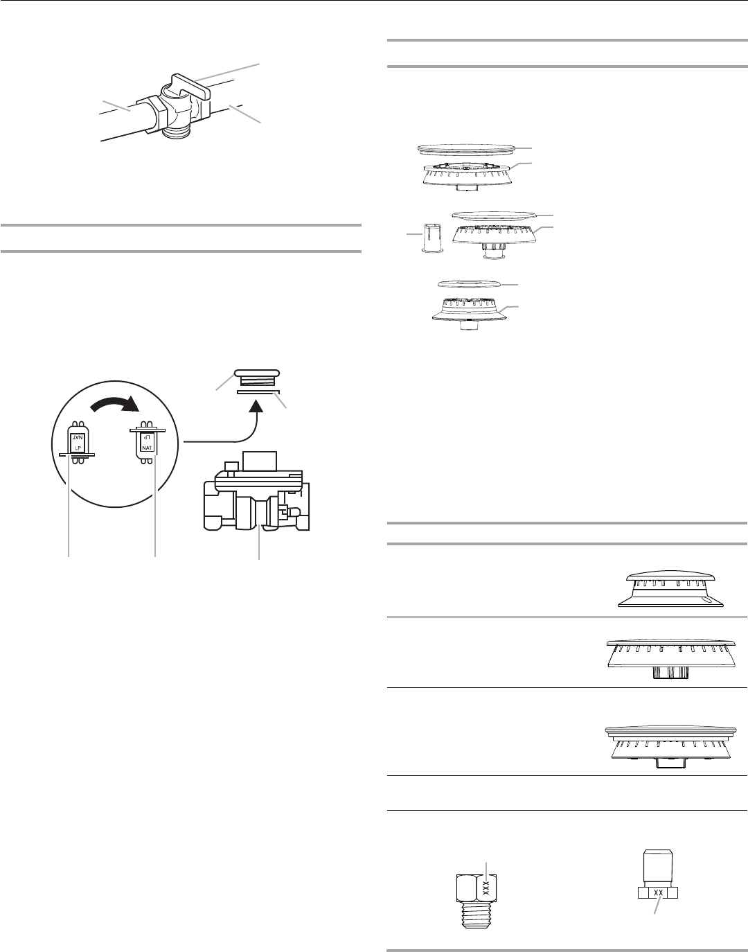
To Convert Surface Burners
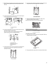
1. If installed, remove the burner grates.
2. Remove burner cap.
3. Remove the burner base.
4. Apply masking tape to the end of a 7 mm nut driver to help
hold the gas orifice spud in the nut driver while changing it.
Insert nut driver into gas opening and press down onto the
gas orifice spud and remove by turning the gas orifice spud
counterclockwise and lifting out. Set gas orifice spud aside.
5. Replace with correct Natural gas orifice spud. See the
“Natural Gas Orifice Spud/Hood Chart.”
Use the following chart to find the exact orifice spud
placement.
Remove choke from medium burner base.
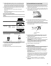
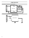
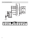
Natural Gas Orifice Spud/Hood Chart
A.To cooktop
B.Shutoff valve (closed position)
C.Gas supply line
A.Access cap
B.Gasket
C.Gas pressure regulator
D.NAT position
E.LP position
A
B
C
A
B
CDE
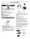
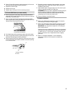
Large Dual Burner
A.Burner cap
B.Burner base
Medium Burner
A.Burner cap
B.Burner base
C.Choke (for use with medium
burner, LP gas only)
Small Burner
A.Burner cap
B.Burner base
Burner Rating Size Burner Style
5,000 BTU 1.01 mm Small burners
15,000 BTU 1.75 mm Medium burners
20,000 BTU 2.10 mm
0.52 mm
Large burner - main
Large burner - simmer
18,000 BTU 1.93 mm Grill burner (on some
models)
Burner orifice spud Grill orifice hood
A.Size stamp or color
A.Size stamp
A
B
A
B
C
A
B
A
A