


7
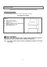
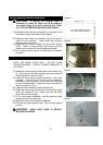
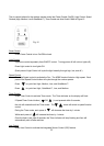
8. Liner is made up of two sections: a large, rear section with
pre-cut for insert and a front section for a total adjustable
depth between 23” and 25-3/4”.
9. Position the rear section of the liner so that it aligns with
the back edge of the custom wood frame. Use a pen to
trace the outline of the pre-cut area. Remove the liner
and proceed to Hood Preparation Before Installation.
10. Install the rear section of the liner with 6 screws (not
included).
11. Install the front section of the liner with 3 screws (not
included)
12. Proceed to Hood Installation on Page 8.
Wiring to Power Supply
SAFETY WARNING
RISK OF ELECTRICAL SHOCK. THIS RANGE HOOD MUST
BE PROPERLY GROUNDED. MAKE SURE THIS IS DONE
BY QUALIFIED ELECTRICIAN IN ACCORDANCE WITH ALL
APPLICABLE NATIONAL AND LOCAL ELECTRICAL
CODES. BEFORE CONNECTING WIRES, SWITCH POWER
OFF AT SERVICE PANEL AND LOCK SERVICE PANEL TO
PREVENT POWER FROM BEING SWITCHED ON
ACCIDENTALLY.
13. Temporarily wire the hood to test for proper operation
before installing. If the insert does not operate, check
the circuit breaker or house fuse. If the insert is still not
working, disconnect the power supply and check the
continuity of all wiring connections.
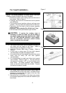
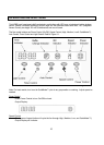
14. Connect electrical wires.
15. Connect three wires (black, white and green) to house
wires and cap with wire connectors. Connect wires
according to their colors (i.e. black to black, white to
white, and green to green).
16. Store wires in the wiring box.
Note: Connect all electrical wires before installing insert.
DO NOT turn on the power until installation is complete.
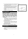
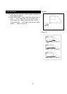
Duct Work Installation
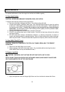
17. Use 8” steel pipe (follow building codes in your area) to
connect the ducting on the hood to the ductwork above.
Use duct tape to seal and secure joints as shown in
Figure 4.
18. Please refer to local codes for the usage of the damper
(not included).
Figure 4