


7
ENG
On installing the kitchen hood make sure
that the Safety Instructions set out on
page 2 are complied with.
•
WARNING: TO REDUCE THE RISK OF
FIRE, ELECTRIC SHOCK, OR INJURY
TO PERSONS, OBSERVE THE
FOLLOWING:
a. Installation work and electrical wiring must
be done by qualified person(s) in accordance
with all applicable codes and standards,
including fire-rated construction.
b. Sufficient air is needed for proper
combustion and exhausting of gases through
the flue (chimney) of fuel burning equipment
to prevent back drafting. Follow the heating
equipment manufacturer´s guideline and
safety standards such as those published by
the National Fire Protection Association
(NFPA), and the American Society for
Heating, Refrigeration and Air Conditioning
Engineers (ASHRAE), and the local code
authorities.
c. When cutting or drilling into wall or ceiling,
do not damage electrical wiring and other
hidden utilities.
d. Ducted fans must always be vented to the
outdoors.
•
WARNING: TO REDUCE THE RISK OF
FIRE, USE ONLY METAL DUCTWORK.
•
WARNING: To Reduce The Risk Of Fire
Or Electric Shock, Do Not Use This Fan
With Any Solid-State Speed Control
Device.
To obtain optimum performance, the external
conduct must not be more than FOUR
METRES LONG, have more than two 90°
angles and its diameter must be at least
Ø120.
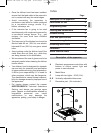
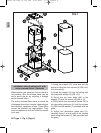
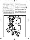
Fig. 1 (Pag. 8)
1) Using the support (O), trace and drill the
points for fitting the lock screws (S) (Ø8 x 45)
onto the ceiling.
2) Screw the support (O) into the ceiling with
the lock screw (S) (Ø8 x 45).
3) Mount the top inner body (A6) in the
support (O) with the screws (Q) (M6 x 16).
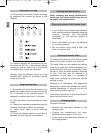
4) Softly attach the decorative handle (W) to
the decorative glass part (U) with the screws
(X) (M5) and the washers (Y) provided with
the glass.
5) Adjust the decorative glass part (U), fixing
it to the body of the kitchen hood using the
screws (V) (M4) provided with the glass.
6) Fit the part (A) if the inner tube (not
supplied) is Ø150 or (A) + (B) if it is Ø120.
7) Attach the inner tube with a clamp (not
supplied) to (A) or (B) as the case may be.
8) Introduce the upper tubecover (A8) into the
lower tubecover (A9).
9) Adjust the group lower tubecover (A9) and
upper tubecover (A8) to the bottom inner body
(A7) and to the decorative glass wing (U).
10) Mount the bottom group to the top, fixing
it to the ceiling with the screws (A10) (M4 x
12) to the desired height.
11) Fit the top part of the inner tube (not
supplied) to the output vent.
12) Lift the upper tubecover (A8) up to the
desired height and fix it to the top group with
the screws (G) (M4 x 12, flat head).
13) Adjust finally the decorative glass part (U),
fixing it to the body of the kitchen hood using
the screws (V) (M4) provided with the glass.
Installation
Installation with output vent
Manual ND ISLA UL ing.qxd 6/05/2003 11:50 PÆgina 7