


9
ENG
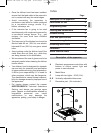
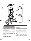
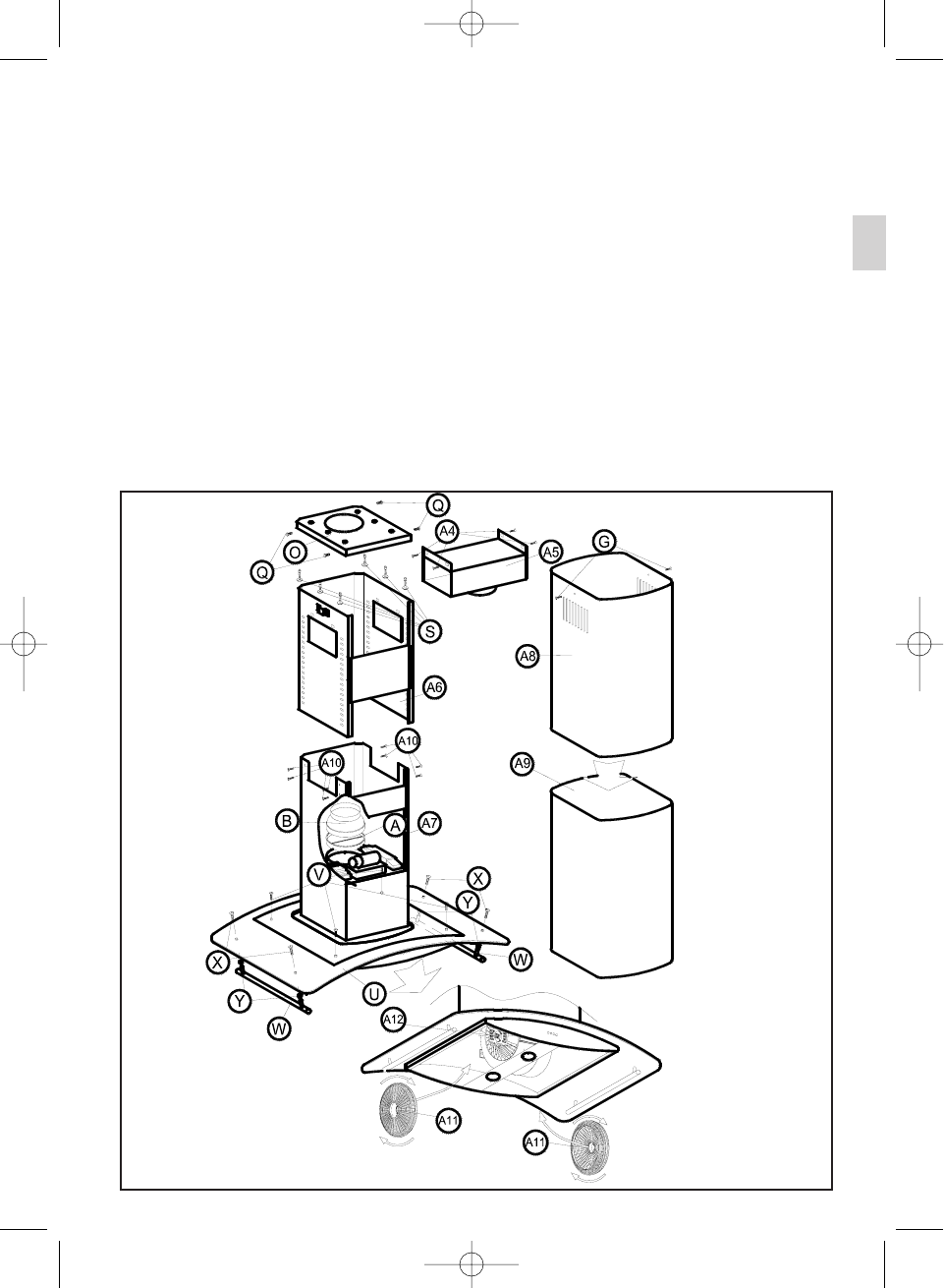
6) Fit the part (A) if the inner tube (not
supplied) is Ø150 or (A) + (B) if it is Ø120.
7) Attach the inner tube with a clamp (not
supplied) to (A) or (B) as the case may be.
8) Introduce the upper tubecover (A8) into the
lower tubecover (A9).
9) Adjust the group lower tubecover (A9) and
upper tubecover (A8) to the botton inner body
(A7) and to the decorative glass wing (U).
10) Fit the circular entrance of the part (A5) to
the top part of the inner tube (not supplied)
with a clamp (not supplied).
11) Mount the bottom group to the top, fixed
to the ceiling with the screws (A10) (M4 x 12)
to the desired height.
12) Mount the part (A5) with the screws (A4)
(M4 x 12) in the rectangle parts of the top
inner body (A6).
13) Lift the upper tubecover (A8) up to the
desired height and fix it to the top group with
the screws (G) (M4 x 12, flat head).
14) Adjust finally the decorative glass part (U),
fixing it to the body of the kitchen hood using
the screws (V) (M4) provided with the glass.
15) Put the filters into the lateral draught
section of the motor making the holes in the
filters match up (A11) with the pivots (A12) of
the motor carcass.
FIG.2
Manual ND ISLA UL ing.qxd 6/05/2003 11:50 PÆgina 9