


10
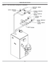
Condensate Drain Requirements
• Pitch condensate drain line down to fl oor drain at mini-
mum of ¼” per foot. External condensate pump (not
furnished) may be used if fl oor drain is not available.
• Condensate pump must be designed for fl ue gas con-
densate application.
• Condensate trap provided with boiler, an additional trap
is not required and should not be used.
• Wood frame or blocks may be used to raise boiler
to maintain drain pitch or to be above external
condensate pump reservoir.
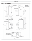
Foundation Requirements
• Install boiler on level surface.
WARNING
Fire hazard. Do not install boiler on carpeting.
Failure to follow these instructions could result in
death or serious injury.
!
• Boiler is NOT to be installed on carpeting.
• If boiler is not level condensate drain lines will not
function properly. Adjustable feet are located on the
boiler to make up for minor surface irregularities or tilt.
• Wood frame or blocks may be used to raise boiler
to maintain drain pitch or to be above external
condensate pump reservoir.
Removal of Existing Boiler From Common Vent
System
When an existing boiler is removed from a common
venting system, the common venting system is likely to be
too large for proper venting of the appliances remaining
connected to it. At the time of removal of an existing boiler,
the following steps shall be followed with each appliance
remaining connected to the common venting system
placed in operation, while the other appliances remaining
connected to the common venting system are not in
operation.
1.
Seal any unused openings in the common venting
system.
2.
Visually inspect the venting system for proper size and
horizontal pitch and determine there is no blockage, or
restrictions, leakage, corrosion and other defi ciencies
which could cause an unsafe condition.
BOILER INSTALLATION
3.
In-so-far as is practical, close all building doors and
windows and all doors between the space in which the
appliances remaining connected to the common venting
system are located and other spaces of the building.
Turn on clothes dryer and any appliance not connected
to the common venting system. Turn on any exhaust
fans, such as range hoods and bathroom exhaust, so
they will operate at maximum speed. Do not operate a
summer exhaust fan. Close fi re dampers.
4.
Place in operation the appliance being inspected.
Follow the lighting instructions. Adjust thermostat so
appliances will operate continuously.
5.
Test for spillage at the draft hood relief opening after 5
minutes of main burner operation. Use the fl ame of a
match or candle, or the smoke from a cigarette, cigar
or pipe.
6.
After it has been determined that each appliance
remaining connected to the common venting system
properly vents when tested as outlined above, return
doors, windows, exhaust fans, fi re place dampers,
and any other gas-burning appliance to their previous
condition of use.
7.
Any improper operation of the common venting system
should be corrected so the installation conforms with
the National Fuel Code, NFPA-54/ANSI -Z223.1 and/
or the Natural Gas and Propane Installation Code,
CAN/CSA B149.1.. When re-sizing any portion of the
common venting system, the common venting system
should be re-sized to approach the minimum size as
determined using the appropriate tables in Chapter 13
of the National Fuel Gas Code, NFPA-54/ANSI- Z223.1
and/or the Natural Gas and Propane Installation Code,
CAN/CSA B149.1.