


35
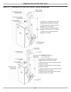
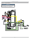
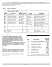
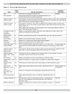
This section provides a brief description of the key controls
and accessories found in this boiler.
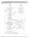
See Figure 26, Page 41 for detailed sequence of operation.
See the Repair Parts Manual for locations of all control
components and accessories described.
Integrated Boiler Control (IBC)
Integrated Boiler Control (IBC) is a microprocessor based
controller for high effi ciency gas boiler that monitors
all safety controls and which controls operation of the
combustion air blower, circulator pump, burner, and
a combination direct spark igniter/fl ame sensor. This
controller is not intended for use with a vent damper.
Controller is mounted on control panel inside of boiler and
contains a three character user interface display.
High Limit Control
High Limit Control determines maximum boiler water
temperature and also provides means for protecting boiler
and heating system from unsafe operating conditions which
could damage boiler.
Limit control sensor is mounted in ¾” NPT control well on
top of the front boiler section at hot water outlet.
Limit control is incorporated in IBC and is fi eld adjustable
between 80°F and 190°F.
Field setpoint adjustment for each installation depends on
heating system requirements.
Limit Control automatically resets when boiler water
temperature decreases (10-30°F adjustable differential).
Differential can be adjusted to provide fl exibility for boiler
operation. Larger the differential, longer run cycle of boiler.
Thermal Purge Operation
1.
Thermal purge feature complies with 2012 DOE
and NRCan requirements that boiler control must
incorporate automatic means to adjust water
temperature.
2.
Intent of thermal purge is to insure usable residual
heat in the boiler is circulated until it is suffi ciently
depleted from the system before the burner is allowed
to fi re. To that end, on call for heat, burner is held
off while circulator runs until boiler temperature drops
to thermal purge temperature limit or time delay is
exceeded. Both of these parameters are adjustable.
3.
When boiler temperature falls below thermal purge
temperature limit or time delay expires, burner is
allowed to fi re.
In addition to thermal purge temperature and thermal
purge time delay parameters, two other conditions release
integrated boiler controller from thermal purge and allow
burner to run in order to maintain comfort in the space.
• Boiler temperature has dropped 10°F from boiler water
temperature measured at beginning of the call for heat.
• Boiler temperature is cooling at a rate greater than
5°F/minute while circulator is running.
4.
For Installations using Indirect Hot Water Heater
Depending on the specifi c installation, thermal purge
delay might or might not affect end user’s expectation for
domestic hot water delivery. In event the customer has a
concern that it takes too long for hot water, the situation
may be resolved in three ways.
A. Add a Domestic Hot Water Module, ECR part
Number 240009562 (Honeywell part number
W8375s1008). This control senses when hot water
is being drawn, and instructs the integrated boiler
control to bypass the thermal purge operation until
domestic how water draw ends. Thermal purge will
then be re-enabled.
DHW module incorporates a temperature sensor
installed at the indirect water heater’s hot water
supply fi tting ( Note - this sensor is in addition to,
not in place of, the limit control on the hot water
tank.) The Module is connected to the Enviracom
terminals in the Integrated Boiler Control.
B. Thermal purge parameters may be adjusted (higher
thermal purge temperature limit and/or shorter
thermal purge time delay) to bring the burner on
sooner.
C. Thermal purge function can be disabled.
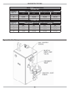
Gas Control Valve
Electrically controlled Combination Gas Control Valve is
designed to meet requirements for use with direct ignition
systems found in this boiler. Valve is piped to gas/air mixer.
Direct Spark Igniter
Direct spark igniter utilizes a spark gap to initiate gas
combustion in the burner. Igniter is mounted next to burner
through gas/air mixer. The igniter also serves as means for
proving main burner fl ame by fl ame rectifi cation. In the
event of a lack of fl ame signal on three (3) consecutive tri-
als for ignition, IBC will lockout and display Error Code 62.
Draft Inducer Temperature Safety Switch
Draft Inducer Temperature Safety Switch is a disc
thermostat (180 °F setpoint) located on induced draft fan
outlet port. Switch protects inducer and vent pipe from
potential high temperature condition for discharging fl ue
gases. Condition would typically be result of higher high
limit control setting or over fi ring. Temperature safety
switch automatically resets when the vent temperature
decreases. (15 °F switch differential).
CONTROLS AND ACCESSORIES