


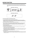
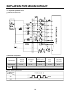
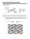
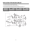

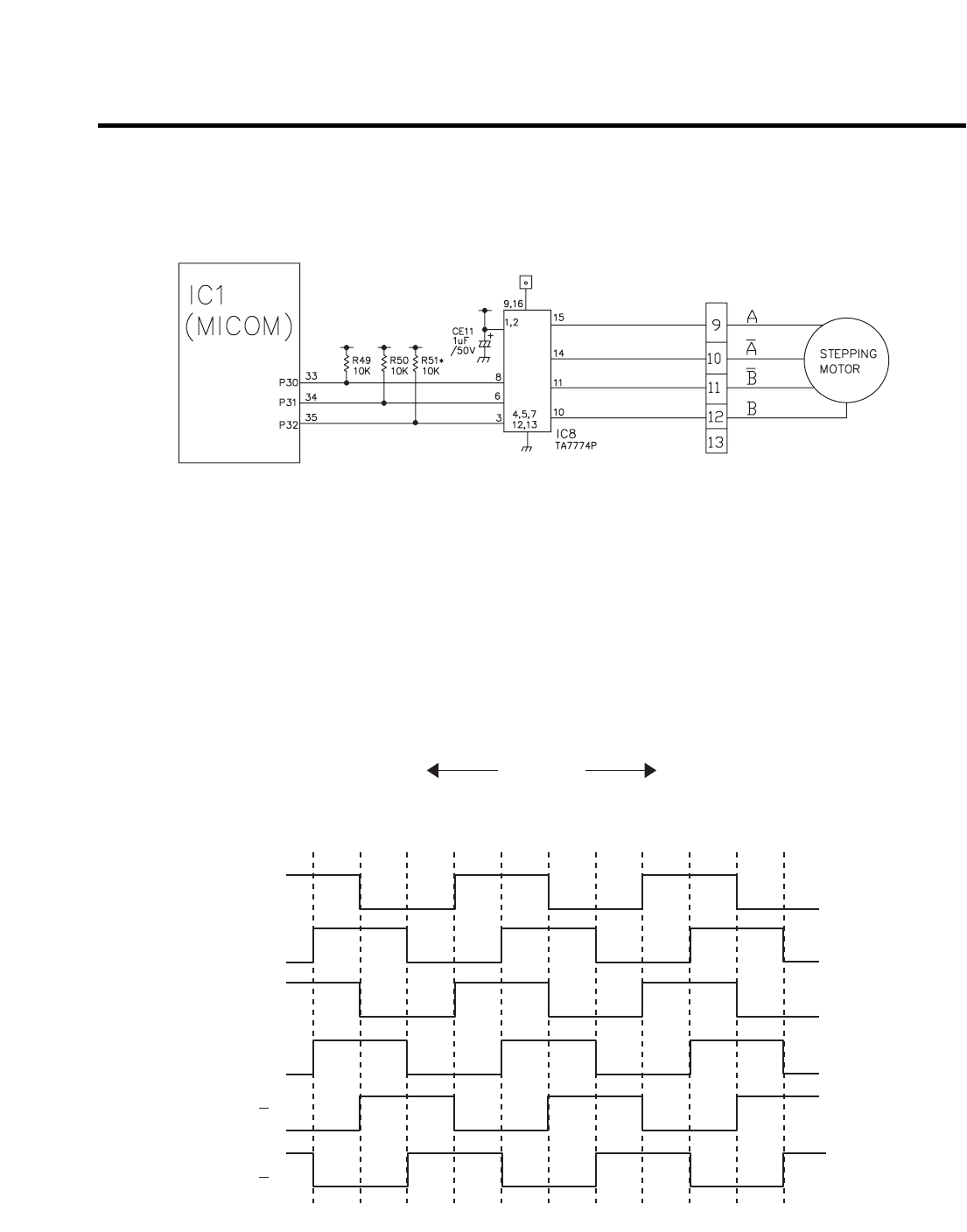
1-10. Stepping motor operation circuit
(1) GR-P227/L227/P257/L257
The motor is driven by magnetism formed in the areas of the coils and the stator. Rotation begins when a HIGH signal is
applied to MICOM Pin 33 of IC10 (TA7774F). This causes an output of HIGH and LOW signals on MICOM pins 34 and 35.
Explanation) The stepping motor is driven by sending signals of 3.33 mSEC via MICOM pins 33, 34, and 35, as shown in
the chart below. These signals are output via terminals 10, 11, 14, and 15 via input terminals 3, 6, and 8 of
IC10 (TA7774F), the motor drive chip. The output signals allow the coils wound on each phase of the stator to
form a magnetic field, which causes rotation. Input to the terminals INA and INB of IC10 as shown in the chart
below drives the motor.
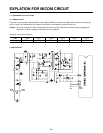
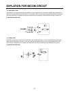
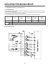
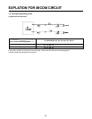
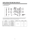
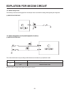
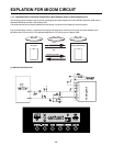
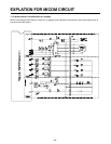
EXPLATION FOR MICOM CIRCUIT
- 33 -
INA
INB
A
B
A
B
CCW (Reverse rotation) (Positive rotation) CW