


MEASUREMENT WITH THE OUTER CASE
REMOVED
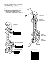
(1) When you replace the magnetron, measure for
microwave energy leakage before the outer case
is installed and after all necessary components
are replaced or adjusted. Special care should be
taken in measuring the following parts.
- Around the magnetron
- The waveguide
WARNING: AVOID CONTACTING ANY HIGH
VOLTAGE PARTS.
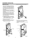
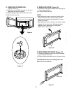
MEASUREMENT WITH A FULLY
ASSEMBLED OVEN
(1) After all components, including the outer
panels, are fully assembled, measure for
microwave energy leakage around the door
viewing window, the exhaust opening and air
inlet openings.
(2) Microwave energy leakage must not exceed the
values prescribed below.
NOTES:
Leakage with the outer panels removed less than
5 mW/cm
2
.
Leakage for a fully assembled oven
(“Before the latch switch (primary) is interrupted”)
with the door in a slightly opened position - less
than 2 mW/cm
2
.
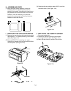
NOTE WHEN MEASURING
(1) Do not exceed meter full scale deflection.
(2) The test probe must be moved no faster than
1 inch/sec (2.5cm/sec) along the shaded area,
otherwise a false reading may result.
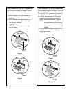
(3) The test probe must be held by the grip portion of
the handle. A false reading may result if the
operator’s hand is between the handle and the
probe.
(4) When testing near a corner of the door, keep
the probe perpendicular to the surface being
tested. (Hold vertically when testing the top and
bottom, and horizontally along the side.)
RECORD KEEPING AND NOTIFICATION
AFTER MEASUREMENT
(1) After adjustment and repair of any microwave
energy interruption or microwave energy blocking
device, record the measured values for future
reference. Also enter the information on the
service invoice.
(2) Should the microwave energy leakage not be
more than 2 mW/cm
2
after determining that all
parts are in good condition, functioning properly
and genuine replacement parts which are listed in
this manual have been used.
(3) At least once a year, have the electromagnetic
energy leakage monitor checked for calibration
by its manufacturer.
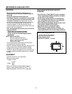
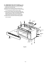
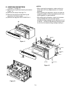
(1)
Microwave power output measurement is made with
the microwave oven supplied at its rated voltage and
operated at its maximum microwave power setting
with a load of (1000±5) g of potable water.
(2)
The water is contained in a cylindrical borosilicate
glass vessel having a maximum material thickness of
1/8” (3 mm) and an outside diameter of
approximately 7.6” (190mm).
(3)
The oven and the empty vessel are at ambient
temperature prior to the start of the test.
(4)
The initial temperature (T1) of the water is (10±2)°C
(50°F) It is measured immediately before the water is
added to the vessel. After addition of the water to the
vessel, the load is immediately placed on the center
of the turntable which is in the lowest position and the
microwave power switched on.
(5)
The time T for the temperature of the water to rise by
a value ∆ T of (10±2)°K is measured, where T is the
time in seconds and ∆T is the temperature rise. The
initial and final water temperatures are selected so
that the maximum difference between the final water
temperature and the ambient temperature is 5°K.
(6)
The microwave power output P in watts is
calculated from the following formula :
4187 x (∆T)
T
is measured while the microwave generator is
operating at full power. Magnetron filament heat-up
time is not included. (about 3 sec)
(7)
The water is stirred to equalize temperature
throughout the vessel, prior to measuring the final
water temperature.
(8)
Stirring devices and measuring instruments are
selected in order to minimize addition or removal of
heat.
7-3
WATER LOAD
TURNTABLE
P =
POWER OUTPUT MEASUREMENT