


21
GNP..6
Instructions for installation and modification
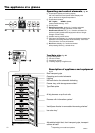
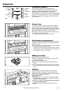
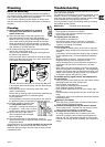
Dimensions
The external dimensions of the appliance can be seen on
fig. S and in the table below.
Gross capacity of appliance (l) Height H (mm)
(see type plate)
188 (20..) 1250
233 (24..) 1447
279 (29..) 1644
324 (33..) 1841
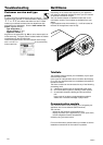
Installation instructions
- Do not install models without side-wall heating side-by-
side with another refrigerator or freezer. This is important
to prevent condensation and consequential damage from
it.
- Models with side-wall heating are designed for side-by-
side installation; they are designed for combination with a
refrigerator.
Contact your dealer for more information.
- Attachment instructions are supplied in the accessories
bag of the appliance with side-wall heating.
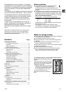
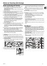
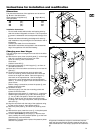
Changing over door hinges
The door hinges can be changed from one side to the other
if required.
W With the door open, lever out plinth panel 1 on the hinge
side with a screwdriver and remove from front.
- Lever out cover 2 with a screwdriver.
Close door.
- Unscrew screw M5 3.
W Pull hinge component 4 with hinge pin 5 out from un-
derneath and remove.
W Open door, lift out at bottom and remove; do not lose the
spacer 6.
W Transfer all hinge components onto the other side:
- Lever out covers 8 with a screwdriver at the front and
remove at an angle from below. Remove hinge pin 7
and insert on the opposite side. Use the hexagon
socket on the open-ended spanner provided (spanner
width 5). Fit covers 8 again: insert at rear and click into
place at front.
- Bottom: Using a screwdriver, remove the spacer 9 and
replace on the other side.
W Re-attach the door:
- Remove plugs bo from the door mounting points and
replace on the other side.
- Suspend door with spacer 6 in hinge pin 7, close door.
- Rotate hinge component 4 by 180°, remove hinge pin
5, turn by 180° and replace. Mount both parts in the
hinge bp: slide the pin into the door mounting through
the hinge, tilt in the hinge component, slide up and attach
with screw 3.
W Align the door flush with the body of the appliance using
the slot on the hinge bp, then tighten screw 3.
W Attach the plinth panel 1 and click into place by press-
ing.
W With the door open, insert the cover 2 in the plinth panel
at the front and click into place at the back.
W Transfer* door handle bl and plugs bm: With the door
open, carefully lift out the pressure plates* bn at the front
and slide away; unscrew handle.
Reassemble in reverse order: replace the pressure plates
and click into position.
_____________________________________________________
All types and models are subject to continuous improve-
ment and the manufacturer therefore reserves the right to
make modifications in the shape, equipment and technolo-
gy.
H
660
704
1287
56,5
683
662
9
5
4
3
2
[mm]
S
10
T
1
T1
14
14
9
SW5
7
6
8
8
*
11
*
10
13
*
12
Torx 15