


21
BN/SBN/es...6
GB
All types and models are subject to continuous improvement
and the manufacturer therefore reserves the right to make
modifications in the shape, equipment and technology.
Instructions for installation
and modification
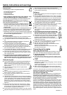
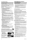
W Re-attach the doors: Remove plugs bp from the door
mounting points and re-place on the other side.
- Suspend top door in hinge pin 7 (with version I, do not
forget to use spacer sleeve 9), close door.
- Slide middle hinge pin 6 into the door mounting from be-
low through the hinge bm. Make sure the door is flush with
the body of the appliance; adjust if necessary using the
slots on the hinge.
- Suspend lower door, close.
- Rotate hinge component 4 by 180°, remove hinge pin 5,
turn by 180° and replace, mind the locking facility. Mount
both parts in the hinge bq: slide the pin into the door mount-
ing through the hinge, tilt in the hinge component, slide up
and attach with screw 3.
W Align the door flush with the body of the appliance using
the slot on the hinge bq, then tighten screw 3.
W Attach the plinth panel 1 and click into place by pressing.
W With the door open, insert the cover 2 in the plinth panel
at the front and click into place at the back.
W Transfer* door handles br and plugs bt. With the door
open, carefully lift out the pressure plates* bs at the front
and slide away; unscrew handle using a Torx
®
or Phillips
screwdriver*.
Re-assemble in reverse order: replace the pressure plates
and click into position.
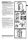
Insertion into row of kitchen units
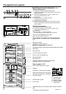
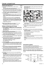
Fig. U. The appliance can be installed in a row of kitchen
units. To adapt the height of the appliance to the surround-ing
furniture a top unit 1 can be added.
A gap of at least 50 mm depth must be provided behind and
along the entire width of this unit so as to ensure sufficient
ventilation. The area of ventilation underneath the ceiling
should be at least 300 cm
2
. The greater the area the more
economically the appliance will run.
W When installing with standard kitchen units (max. depth
580 mm), the appliance can be set up right next to the
kitchen unit. The door protrudes 34 mm from the side of the
kitchen unit and 51 mm at the front. This enables it to be
opened and closed without difficulty.
W When setting up the appliance next to a wall 4, a minimum
distance of 36 mm must be provided on the hinge side
between the appliance and the wall (for the handle when
the door is open).
1 top unit 3 kitchen unit side panel
2 refrigerator/freezer 4 wall
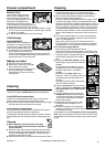
S
[mm]
1841
597
631
614
644
1179
56,5
10
T
SW5
*
SW5
180°
1
2
3
4
5
6
7
9
9
8
8
8
8
10
11
12
13
15
I
II
*
18
20
20
21
21
9
T1
15
13
*
16
*
17
14
7
25
25
Torx 15
580
631
min.
50
ca. 36
[mm]
min.
300 cm
2
U
4
3
2
1
9
25
20
Torx 25
Instructions for installation
and modification