


21
GB
* Depending on model and options
Instructionsforinstallationandmodication
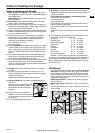
Dimensions
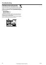
The external dimensions of the appliance can be seen on g.
S and in the table below.
Gross capacity of appliance (l)
Height H (mm)
(see type plate)
___________________________________________________
188 (20..) 1250
233 (24..) 1447
279 (29..) 1644
324 (33..) 1841
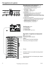
Installation instructions
Do not install the appliance side-by-side with another refrig-
erator or freezer. This is important to prevent condensation
and consequential damage from it.
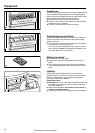
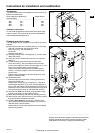
Changing over door hinges
The door hinges can be changed from one side to the other if
required.
W
With the door open, lever out plinth panel
1 on the hinge
side with a screwdriver and remove from front.
-
Lever out cover
2 with a screwdriver.
Close door.
-
Unscrew screw M5
3.
W Pull hinge component
4 with hinge pin 5 out from under-
neath and remove.
W
Open door, lift out at bottom and remove; do not lose the
spacer
6.
W Transfer all hinge components onto the other side:
-
Lever out covers
8 with a screwdriver at the front and
remove at an angle from below. Remove hinge pin
7 and
insert on the opposite side. Use the hexagon
socket on the open-ended spanner provided (spanner
width 5). Fit covers
8again: insert at rear and click into
place at front.
-
Bottom: Using a screwdriver, remove the spacer
9 and
replace on the other side.
W
Re-attach the door:
- Remove plugs
bo from the door mounting points and re-
place on the other side.
-
Suspend door with spacer
6in hinge pin 7, close door.
- Rotate hinge component
4 by 180°, remove hinge pin 5,
turn by 180° and replace. Mount both parts in the hinge
bp:
slide the pin into the door mounting through the hinge, tilt in
the hinge component, slide up and attach with screw
3.
W Align the door ush with the body of the appliance using
the slot on the hinge
bp, then tighten screw 3.
W Attach the plinth panel
1and click into place by press-ing.
W With the door open, insert the cover
2in the plinth panel at
the front and click into place at the back.
W
Transfer* door handle
bl and plugs bm: With the door
open, carefully lift out the pressure plates*
bn at the front
and slide away; unscrew handle.
Reassemble in reverse order: replace the pressure plates
and click into position.
________________________________________________
All types and models are subject to continuous improvement
and the manufacturer therefore reserves the right to make
modications in the shape, equipment and technology.
H
660
704
1287
56,5
683
662
9
5
4
3
2
[mm]
S
10
T
1
T1
14
14
9
SW5
7
6
8
8
*
11
*
10
13
*
12
Torx 15
GNP..06