


Impinger II – Installation & Operation Manual
5
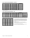
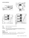
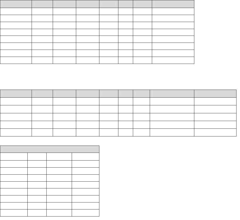
UTILITY SPECIFICATIONS REQUIRED – ELECTRIC
*Model Energy Power Voltage Current Phase Hz
Recommended
Electrical Specification
1130-xxx-E-Kxxx Electric 10kW 120/208V 48 Amps 1 60 Hz 4 Wires, 2 Pole + N + G
1131-xxx-E-Kxxx Electric 10kW 120/240V 42 Amps 1 60 Hz 4 Wires, 2 Pole + N + G
1132-xxx-E-Kxxx Electric 10kW 120/208V 28 Amps 3 60 Hz 5 Wires, 3 Pole + N + G
1133-xxx-E-Kxxx Electric 10kW 120/240V 25 Amps 3 60 Hz 5 Wires, 3 Pole + N + G
1151-xxx-E-Kxxx Electric 10kW 200V 29 Amps 3 50/60 Hz 4 Wires, 3 Pole + G
1161-xxx-E-Kxxx Electric 10kW 120/240V 42 Amps 1 60 Hz 4 Wires, 2 Pole + N + G
1162-xxx-E-Kxxx Electric 10kW 120/208V 28 Amps 3 60 Hz 5 Wires, 3 Pole + N + G
1164-xxx-E-Kxxx Electric 10kW 400V 42 Amps 3 50 Hz 5 Wires, 3 Pole + N + G
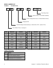
* REFERENCE MODEL NUMBER KEY
UTILITY SPECIFICATIONS REQUIRED – GAS
Model Energy Power Voltage Current Phase Hz
Recommended
Electrical Specification
Gas
1116-xxx-E-Kxxx Nat. Gas 40,000 BTU 120 VAC 7 Amps 1 60 Hz 3 Wires, 1 Pole + N + G
40,000 BTU at 7 inches,
H
2
O column**
1117-xxx-E-Kxxx L.P. Gas 40,000 BTU 120 VAC 7 Amps 1 60 Hz 3 Wires, 1 Pole + N + G
40,000 BTU at 11 inches,
H
2
O column**
1154-xxx-E-Kxxx Nat. Gas H
s
13 KW 230 VAC 2 Amps 1 50 Hz 3 Wires, 1 Pole + N + G
H
s
13 KW/HR at 1.7 kPa,
H
2
O column**
1155-xxx-E-Kxxx L.P. Gas H
s
13 KW 230 VAC 2 Amps 1 50 Hz 3 Wires, 1 Pole + N + G
H
s
13 KW/HR at 2.73
kPa, H
2
O column**
1178-xxx-E-Kxxx Nat. Gas 40,000 BTU 120 VAC 7 Amps 1 60 Hz 3 Wires, 1 Pole + N + G
40,000 BTU at 7 inches,
H
2
O column**
GAS PRESSURE CONVERSION CHART
Inches of
Water Column
KPa m-Bar
Millimeters of
Water Column
3.5 0.87 8.70 88.9
4.5 1.12 11.2 114.3
7 1.74 17.40 177.8
10 2.48 24.87 254.0
10.5 2.61 26.11 266.7
11 2.73 27.36 279.4
14 3.48 34.81 355.6
14.5 3.61 36.05 368.3
** NOTE: For proper operation, the gas valve requires a nominal inlet pressure of 7
inches of H
2
O for natural gas and 11 inches of H
2
O column for L.P. gas. A minimum
inlet pressure of 1.0 inch of H
2
O column above the manifold setting (NAT. manifold
3.5” H
2
O, L.P. manifold 10” H
2
O) must be maintained with no pressure drop from the
no load to full load condition. The maximum inlet pressure must be maintained at or
below ½ PSIG (14.5 inches H
2
O column). Refer to the chart on the left for pressure
conversions.
Electrical Supply for Australia:
Single Phase: 240 VAC, 50 Hz / 20 Amp; one neutral & one earth/ground.
Three Phase: 240/415 VAC / 20 Amp; three active, one neutral & one earth/ground.
All ovens require separate service and dedicated neutral.
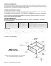
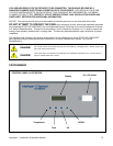
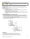
NOTE: Do not install the (these) oven(s) in any area with an ambient temperature in
excess of 95°F / 35° C. Doing so will cause damage to the unit.