


Impinger II – Advantage Digital Service Manual - Domestic
8
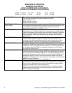
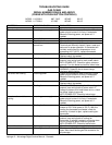
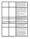
Main fan If not operating, refer to “Oven fan will not run”.
Centrifugal switch of main fan
motor
Check for 120VAC at wire #5 (input to centrifugal
switch, located at 6-pin connector in raceway near
the main fan motor) to neutral. If no voltage is
present, trace wiring back to the main power
switch. If voltage is present, check for 120VAC at
wire #22 (output of centrifugal switch) to neutral. If
no voltage is present at #22, and the motor is
running, replace the main fan motor.
Hi-limit thermostat,
oven cavity
Terminals are normally closed. If open, reset
thermostat and retest. If thermostat will not hold
for maximum oven temperature, and oven is not
exceeding temperature setting, check for proper
location of capillary bulb in its spring holder. If the
capillary checks okay, replace the hi-limit
thermostat.
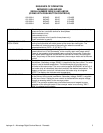
Burner blower motor Check for 120VAC supplied to burner blower
motor at wire #13 to neutral. If no voltage is
present, trace wiring back to the main power
switch. If voltage is present, and the motor is not
running, check for opens, shorts or grounds.
WITH POWER OFF: Turn motor to check for
locked rotor.
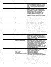
Burner transformer Check for 120VAC supplied to the primary of the
burner transformer. If no voltage is present, trace
wiring back to the oven cavity hi-limit thermostat.
If voltage is present, check for 24VAC at
transformer secondary. If there is primary voltage
but no secondary voltage, replace burner
transformer.
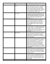
Centrifugal switch of burner
blower motor
Check for 24VAC at motor connector, wire #13 to
neutral. If voltage is not present, trace wiring back
to transformer. If voltage is present, check for
voltage at wire #14 to neutral. If no voltage is
present at wire #14, and motor is running, replace
burner blower motor.
Ignition control Check for 24VAC at ignition control terminals
marked “24V”, if no voltage is present, trace wiring
back to centrifugal switch. Check for 120VAC to
ignition control at terminal “L1” to neutral. If no
voltage is present, trace wiring back to main
power switch. When 24VAC is supplied to the
ignition control, the ignition control switches
120VAC to the hot surface igniter If 24VAC and
120VAC are supplied to ignition control, but there
is no voltage at the hot surface igniter, replace the
ignition control.
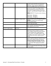
Hot surface igniter If 120VAC is present at hot surface igniter
terminals, visually check to see that the igniter is
heating (igniter may be viewed through the port in
the end of burner tube). The igniter should glow
bright red. If the igniter does not heat, replace the
hot surface igniter.
Ignition control After 45 seconds of hot surface igniter pre-heat,
the ignition control will switch 23VAC to the gas
control valves. Check for 24VAC output from
ignition control across terminals marked “valve”
and “valve gnd”. If no voltage is present, replace
ignition control.
Gas control valves When 24VAC is supplied to the gas control