


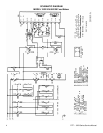
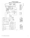

DTF – 1920 Series Service Manual
12
CAPACITOR, CONVEYOR MOTOR – REPLACEMENT
1. Shut off power at main breaker.
2. Remove control box top. Remove tube from air pressure switch.
3. Remove wiring from air pressure switch and conveyor motor capacitor and mark all
wires for reassembly.
4. Remove two screws and remove air pressure switch/capacitor mounting bracket.
5. Remove capacitor from mounting bracket.
6. Reassemble in reverse order and check system operation.
CONVEYOR MOTOR – REPLACEMENT
1. Shut off power at main breaker.
2. Remove coupling from conveyor shaft (one screw at end of motor shaft).
3. Remove control box top and rear control box cover.
4. Remove three screws and remove main control board and mounting bracket.
5. Disconnect wiring for motor and remove motor mounting screws. Remove conveyor
motor and mounting bracket.
6. Remove conveyor motor from mounting bracket.
7. Reassemble in reverse order and check system operation.
AIR PRESSURE SWITCH – REPLACEMENT
1. Shut off power at main breaker.
2. Remove control box top. Remove tube from air pressure switch.
3. Remove wiring from air pressure switch and conveyor motor capacitor and mark all
wiring for reassembly.
4. Remove two screws and remove air pressure switch/capacitor mounting bracket.
5. Remove air pressure switch from mounting bracket.
6. Reassemble in reverse order and check system operation.
AIR PRESSURE SWITCH – ADJUSTMENT
1. Apply power to machine, set temperature control to maximum temperature.
2. Allow 30 minute preheat. Adjust air pressure switch so that switch will stay closed at
maximum temperature.
3. Remove air tube from air pressure switch and verify that switch opens.
4. Reconnect air tube and check system operation.
THERMOCOUPLE – REPLACEMENT
1. Shut off power at main breaker.
2. Remove control box top. Remove rear cover. Remove right side heating element cover.
3. Remove mounting screws and remove thermocouple from oven cavity.
4. Disconnect thermocouple from main control, remove thermocouple.
5. Remove connector plug from new thermocouple and mark wires for reassembly. Install
thermocouple and reassemble plug connector.
6. Reassemble in reverse order and check system operation.