DTF – 1920 Series Service Manual
13
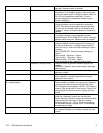
THERMOCOUPLE MEASUREMENT
TEMPERATURE (°F) D.C. MILLIVOLTS
200° 2.8
250° 4.0
300° 5.1
350° 6.0
400° 7.1
450° 8.2
500° 9.3
550° 10.4
600° 11.5
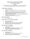
THERMOSTAT, HI-LIMIT – REPLACEMENT
1. Shut off power at main breaker.
2. Remove rear cover, remove right side heating element cover.
3. Remove hi-limit thermostat from the mounting bracket. Remove mounting nut from hi-
limit thermostat. Remove hi-limit thermostat.
4. Form 90° bend in hi-limit thermostat.
5. Reassemble in reverse order and check system operation. Be sure to reset thermostat
before testing.
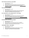
HEATING ELEMENT, MAIN – REPLACEMENT
1. Shut off power at main breaker.
2. Remove conveyor, finger assemblies and plenum front. Remove rear cover and
appropriate heating element cover.
3. Remove wires from heating element and mark wiring for reassembly.
4. Remove mounting screws and remove heating element.
5. Reassemble in reverse order and check system operation.
HEATING ELEMENT, INFRARED – REPLACEMENT
1. Shut off power at main breaker.
2. Remove conveyor and lower finger assemblies. Remove front conveyor support from
oven cavity.
3. Remove front cover and heating element cover. Disconnect wiring from heating element
and mark wires for reassembly.
4. Reassemble in reverse order and check system operation.
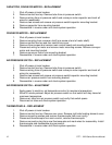
MAIN CONTROL – REPLACEMENT
1. Shut off power at main breaker.
2. Remove control box top, front panel and rear control box cover.
3. Remove display board from front panel by pulling board off of it’s mounting pins.
4. Remove three screws from main control mounting bracket and remove main control board
and its mounting bracket. Remove main control from it’s mounting bracket by pulling the
control from the mounting bracket.
5. When installing new control, be sure to use ground strap so that there is no static
electricity. When installing new control, be sure to set the jumpers on the control for proper


