


Impinger X2 – Analog Service Manual – Dom & Int’l14
On at this time
Electronic temperature
control
control at terminals #13 and #12. Of there is no voltage,
trace wiring back to the burner switch. Also check for
supply voltage to terminal #20 on the electronic
temperature control. If there is no voltage at terminal
#20, trace wiring back to terminal #13. Set temperature
control to maximum temperature and check for output
voltage at terminal #21 and neutral. If voltage is present
at terminal #20 and neutral, and the unit is not heating,
refer to “Temperature regulation valve” for next check.
If voltage is not present, proceed.
Thermocouple probe WITH POWER ON AND THERMOCOUPLE LEADS
ATTACHED TO THE ELECTRONIC TEMPERATURE
CONTROL: Measure the D.C. millivolt output of these
leads. Refer to chart in the “Removal, Installation and
Adjustment” section for proper readings. If these
readings are not achieved, replace thermocouple.
Burner control. Check for supply voltage to main valve. If no voltage is
present, trace wiring back to burner control. If there is
no voltage output, replace burner control.
Main gas valve Check for supply voltage to main valve. If there is
voltage present, check to see that valve is opening.
Connect manometer to pressure tap on outlet side of
valve. If there is voltage to the valve, but no output gas
pressure, replace the valve.
Temperature regulation valve If supply voltage is present on the electronic
temperature control, terminal #13 to neutral, check for
voltage at temperature regulation valve. If no voltage is
present, trace wiring back to electronic temperature
control, terminal #20. If voltage is present, listen for
valve to open and close. Also check for opens or shorts
in the operating coil. Replace temperature regulation
valve as needed.
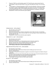
Intermittent heating Thermal/Overload of main fan
and burner blower motors
The main fan motor and burner blower motor are
equipped with internal thermal protection and will cease
to operate if overheating occurs. As the motors over-
heat and then cool, this will cause the units to cycle on
and off intermittently. Improper ventilation or lack of
preventive maintenance may cause this. Also, most of
the problems listed under “Oven will not heat” can
cause intermittent failure.
Conveyor will not run NOTE: The ovens may contain two, three or four conveyor drive systems using like
components. The trouble shooting sequence will be the same for each of the conveyor
drive systems
Power supply Check circuit breakers, reset if required. Check power
plug to be sure it is firmly in receptacle. Measure
incoming power, call power co. if needed.
Switch, oven fan Check continuity between switch terminals. Replace
switch as needed.
Relay, main fan Check for supply voltage to relay terminal #13. If
voltage is not present, trace wiring back to power
supply. If voltage is present, check for supply voltage at
terminal #14. If there is no voltage at terminal #14, and
the relay is energized, replace the main fan relay.
Fuse, 2 Amp Check, replace if necessary.
Fuse holder Check for supply voltage to fuse holder. If no voltage is
present, trace wiring back to main fan relay. Check fuse
holder, replace if necessary.
Switch, conveyor Check for supply voltage to conveyor switch. If no
voltage is present, trace wiring back to fuse holder.
Check continuity between switch terminals. Replace