


Impinger X2 – Analog Service Manual – Dom & Int’l 13
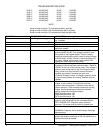
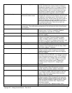
Burner control Check for supply voltage at terminal #7 on burner
control. If no voltage is present, trace wiring back to air
pressure switch. If voltage is present, check for output
voltage (after the 30 second delay) from terminal #8 on
the burner control. If there is no output voltage from
terminal #8, (after the 30 second delay) replace the
burner control. If there is output voltage, proceed.
Pilot valve Check for supply voltage to pilot valve. If no voltage is
present, trace wiring back to burner control. If voltage is
present, check for gas pressure at the pilot line
connection. If no gas pressure is present during
ignition, check for any blockage in the assembly. If
there are no obstructions, and there is gas supplied to
the oven, replace the gas valve.
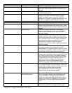
Burner control Check to see that the high voltage igniter circuit on the
burner control is energized. To check, turn power off,
disconnect the igniter lead from the burner control. Turn
power on. If no spark is visible, replace burner control.
If a spark is visible at burner control, proceed.
Burner igniter Check the burner igniter head for any damage or
obstructions also check for frayed or broken wire.
Check spark gap, gap should be 3/32” If there is visible
damage, replace burner igniter.
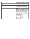
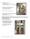
No pilot flame If there is supply voltage to the burner control, and the
pilot valve and igniter circuits are energized, visually
check for a pilot flame. This may be done by looking
through the inspection view port on the end of the
burner. If no pilot flame is visible, check the pilot tube.
Pilot tube Check for gas pressure at the pilot tube. Disconnect
pilot tube at the burner and connect manometer to pilot
tube. If no gas pressure is present during ignition,
check for blockage of the pilot tube. If the pilot tube is
clear, proceed.
Pilot orifice If there is gas pressure at the pilot tube, check the pilot
orifice for blockage or obstructions. Replace pilot orifice
as needed.
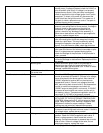
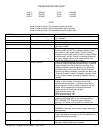
Burner igniter Check the burner igniter head for any damage or
obstructions also check for frayed or broken wire.
Check spark gap, gap should be 3/32” If there is visible
damage, replace burner igniter.
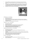
Flame sensor (There should be a visible pilot flame at this time.)
To check for proper flame sensor operation, connect a
digital multimeter (capable of measuring D.C. micro
amps) in series between the flame sensor wire
(normally connected to terminal #13 on the burner
control) and terminal #13 on the burner control. With a
visible pilot flame, the current reading should be 0.7
micro amp minimum. NOTE: The D.C. micro amp test
must be conducted with the oven in low flame operation
only. If these values are not achieved, replace flame
sensor. Also check for any type of damage to flame
sensor wire and connections.
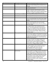
Power supply If there is a pilot flame, and there is sufficient micro
amp. current, but the flame will not stay on, check for
proper polarity of the power supply.
Burner control If there is sufficient micro amp current, and there is
proper polarity of the power supply, but the burner will
not stay on, check the reset button for the burner
control. If the reset switch checks okay, replace the
burner control.
Pilot flame, but no main flame NOTE: Flame should be Check for supply voltage to electronic temperature