


Impinger X2 – Analog Service Manual – Dom & Int’l 7
bearings. Replace bearings as needed.
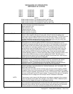
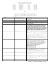
Oven will not heat Gas supply Check for adequate gas supply to oven.
Manual gas shut off valve Check to see that the manual gas shut off valve is
open. Also, check flexible gas line connection for any
damage.
Main fan motor Check for main fan operation. If it is not operating, refer
to “Oven fan will not run”.
Relay, main fan Check for 120VAC supplied to relay terminal #13. If
voltage is not present, trace wiring back to power
supply. If voltage is present, check for 120VAC at
terminal #14. If there is no voltage at terminal #14, and
the relay is energized, replace the main fan relay.
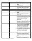
Fuse, 2 Amp, control (F8) Check, replace if necessary.
Fuse holder Check, replace if necessary.
Switch, oven fan Check for 120VAC to the switch, if no voltage is
present, trace wiring back to the main fan relay. Check
continuity between switch terminals. Replace switch as
needed.
Switch, burner Check for 120VAC to the switch, if no voltage is
present, trace wiring back to the oven fan switch.
Check continuity between switch terminals. Replace
switch as needed.
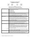
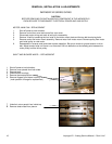
Air pressure switch Check for 120VAC to the air pressure switch. If no
voltage is present, trace wiring back to burner switch.
This normally open switch should close when the main
fan is activated. Check air switch tube for blockage or
any obstructions, repair as needed. Refer to the
“Removal and installation” section for proper
adjustment of air pressure switch. Replace air pressure
switch as needed.
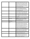
Transformer, burner Check for 120VAC supplied to primary of transformer. If
no voltage is present, trace wiring back to the air
pressure switch. If voltage is present, check for 24VAC
at transformer secondary. If there is primary voltage but
no secondary voltage, replace burner transformer.
Relay, burner blower Check for 24VAC supply to relay coil. If no voltage is
present, trace wiring back to burner transformer. Check
for 120VAC to relay contact. If no voltage is present,
trace wiring back to air pressure switch. When 24VAC
is applied to the coil, there will be a delay of 20 – 30
seconds. After this time delay, the relay contacts
should close. If there is 24VAC applied, but the
contacts do not close, replace the burner blower relay.
Motor, burner blower Check for 120VAC supplied to the burner blower motor.
If no voltage is present, trace wiring back to the burner
blower relay. If voltage is present, and the motor is not
turning, check for opens, shorts or grounds.
WITH POWER OFF: Check for locked rotor.
Replace burner blower motor as needed.
Centrifugal switch of
Burner blower motor
Check for 24VAC supplied to centrifugal switch at wire
S5. If no voltage is present, trace wiring back to the
burner transformer. If voltage is present, check for
24VAC out of centrifugal switch at wire #32. If there is
voltage in, but there is no voltage out, and the burner
blower motor is running, replace the burner blower
motor.
Burner control Check for 24VAC supplied to the burner control at
terminals #5 and #6. If no voltage is present, trace