


18
CDVX Series Direct Vent Gas Fireplace
20012253
1
2
3
4
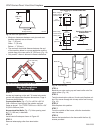
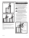
1 + 2 + 3 + 4 = 270
o
CFM132
Insert Rear Vent Sidewall
2/26/01 sta
CFM132
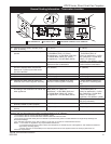
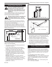
Fig. 29 Maximum number of elbows.
Example:
Elbow 1 = 90˚
Elbow 2 = 45˚
Elbow 3 = 45˚
Elbow 4 = 90˚
Total angular variation = 270˚
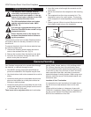
•IMPORTANT• Minimum clearance between vent
pipes and
combustible materials is one (1”) inch (25 mm)
on bottom, sides and top.
Twist Lock Vent Starter Kit 7TCRVT, plus
Elbow 7TCDV90 must be used in Vertical
Sidewall installations.
Canadian & USA Installations:
The venting system must conform with local codes, or
in the absence of local codes, with National Fuel Gas
Code, ANSI Z223.1/NFPA 54 - latest edition, or CSA
B149.1 Installation Code.
Only MHSC venting components specifically approved
and labelled for this fireplace may be used
.
Vertical Sidewall Installation
STEP 1
Locate vent opening on the wall. It may be necessary
to first position the fireplace and measure to obtain hole
location. Depending on whether the wall is combustible
or noncombustible, cut opening to size. (Page 14, Fig.
17)
For combustible walls first frame in opening.
Combustible Walls (Fig. 17): Cut a 9³⁄₈”H x 9³⁄₈” W
(240 x 240 mm) hole through the exterior wall and
frame. For 7TCRVT1320 cut a 10³⁄₈”H x 9³⁄₈” W (264 x
240 mm) hole.
Noncombustible Walls
(Fig. 17): Hole opening must
be 7.5” (190 mm) in diameter.
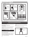
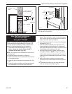
STEP 2
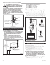
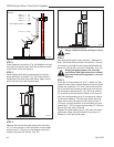
Slide venting component on collar of fireplace. Secure
component to fireplace by running a screw (self-tap-
ping) through tab & into outer casing. (Fig. 30)
�
CFM143
2/2/01 sta
Ensure Pipes are
Concentric
CFM143a
Fig. 30 Always start vertical run with 7TCDV90 on 36CDVR
unts.
7TCDV90
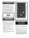
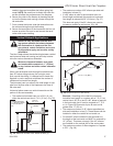
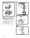
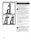
STEP 3
Measure the horizontal length requirement including a
2” (51 mm) overlap, i.e. from the elbow to the outside
wall finish plus 2”, or the distance required if installing a
second 90° elbow. (Fig. 31)
CFM136
Rear Vent horizontal length
2/26/01 sta
X
Always install hori-
zontal venting on a
level plane.
CFM136
Fig. 31 Measure horizontal length including 2” overlap.
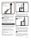
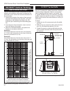
STEP 4
Use appropriate length of pipe section - telescopic or
fixed - and install the horizontal vent sections. A starter
section of pipe which goes through the wall is packaged
with the 7TCRVT kit, and can be cut to suit if necessary.
(Fig. 32)
Sealing between the vent pipe and firestop
with high temperature sealant will restrict
cold air being drawn in around fireplace.
STEP 5
Guide the vent termination’s 4” and 7”
collars into their
respective vent pipes. Double check that the vent pipes
overlap the collars by 2” (51 mm). Secure the termination
to the wall with screws provided and caulk around the
wall plate to weatherproof. (Fig. 33)