


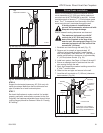
22
CDVX Series Direct Vent Gas Fireplace
20012253
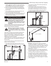
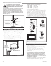
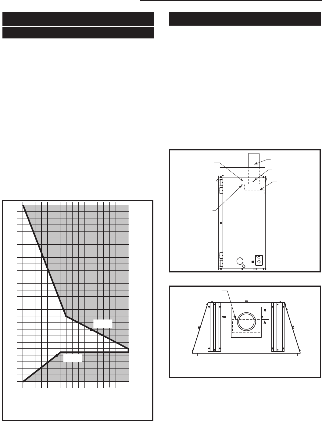
How to Use the Vent Graph
The vent chart should be read in conjunction with the
following vent installation instructions to determine the
relationship of the vertical and horizontal dimensions of
the vent system.
1. Determine the height of the center of the horizontal
vent pipe exiting through the outer wall. Using this
dimension on the Sidewall Vent Graph (Fig. 42),
locate the point intersecting with the slanted graph
line.
2. From the point of this intersection, draw a vertical
line to the bottom of the graph.
3. Select the indicated dimension, and position the
fireplace in accordance with same.
Example A:
If the vertical dimension from the floor of the fireplace
is 11’ (3.4 m) the horizontal run to the face of the outer
wall must not exceed 14’ (4.3 m).
Example B:
If the vertical dimension from the floor of the unit is 7’
(2.14 m), the horizontal run to the face of the outer wall
must not exceed 8¹⁄₂’ (2.6 m).
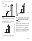
36CDVXT Vertical Venting
Horizontal dimension from the outside face of the
wall to the center of the fireplace vent flange
Sidewall vent graph showing the relationship between vertical
and horizontal dimensions for a Direct Vent flue system.
Vertical dimension from the floor of the unit
to the center of the horizontal vent pipe
3
4
5
6
7
8
9
10
11
12
13
14
15
16
17
18
19
20
21
22
23
24
25
26
27
28
29
30
3 4 5 6 7 8 9 10 11 12 13 14 15 16 17 18 19 20
eg: A
eg: B
CFM102
DV Graphic
9/28/00 sta
Fig. 42 Sidewall venting graph. (Dimensions in feet)
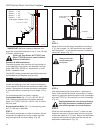
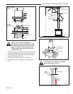
36 CDVXT Top Vent Baffle
The 36CDVXT is shipped with a restrictor installed in
the unit. This allows for a better flame when installing a
vertical venting configuration. Below is a rough esti-
mate of opening positions based on vent length. This
is a guide. More fine tuning can be done by a qualified
installer. Adjust the restrictor so there is no lifting of the
flame from the burner tube and the flame is not dirty to
create soot.
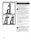
To adjust:
1. Loosen the two (2) screws securing the flue baffle.
(Fig. 43)
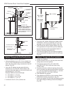
2. Remove two (2) screws from either side of the flue
box. (Fig. 43) Adjust the restrictor. (Fig. 44)
3. Tighten the screws in the flue baffle and insert the
two (2) screws removed earlier through the slots in
the restrictor.
Loosen
Screws
Flue Baffle
Flue Pipe
FP1797
Fig. 43 Loosen screws securing flue baffle.
Remove Screws
from Either side
Flue Box
X
FP1799
CDVXT restrictor
4/07
Restrictor
FP1799
Fig. 44 Adjust the restrictor for best flame appearance.
Up to 10’ (3 m) X = 1
¹⁄₂” (38 mm)
10’ to 40’ (12 m) X = 1
¹⁄₄” (32 mm)