Installation Instructions Section 2
2-4
Part Number 80-1560-3
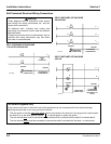
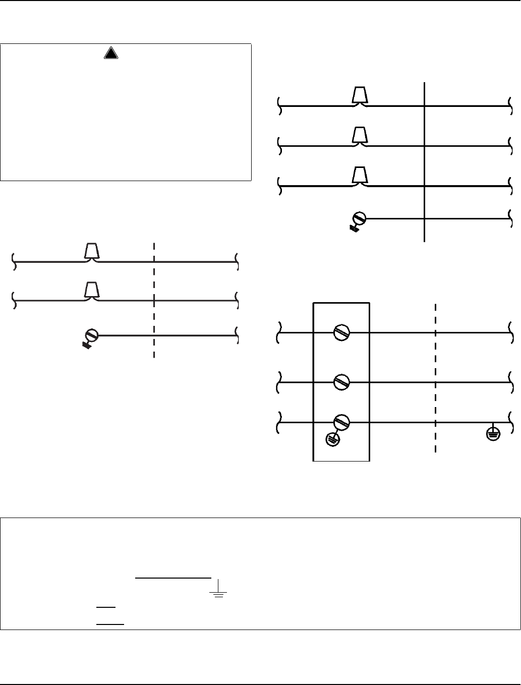
Self-Contained Electrical Wiring Connections
SELF CONTAINED ICE MACHINE
115/1/60 OR 208-230/1/60
SELF CONTAINED ICE MACHINE
208-230/3/60
SELF CONTAINED ICE MACHINE
230/1/50
!
Warning
These diagrams are not intended to show proper
wire routing, wire sizing, disconnects, etc., only the
correct wire connections.
All electrical work, including wire routing and
grounding, must conform to local, state and national
electrical codes.
Though wire nuts are shown in the drawings, the ice
machine field wiring connections may use either
wire nuts or screw terminals.
L
1
L
1
N=115V
OR
L2=208-230V
GROUND
GROUND
ICE MACHINE
CONNECTIONS
SV1258
TO SEPARATE
FUSE/BREAKER
L
1
L
1
GROUND
GROUND
ICE MACHINE
CONNECTIONS
TO SEPARATE
FUSE/BREAKER
L
2
L
3
L
2
L
3
SV1190
L
1
L
1
N
N
GROUND
GROUND
ICE MACHINE
CONNECTIONS
TO SEPARATE
FUSE/BREAKER.
DISCONNECT ALL
POLES.
SV1191
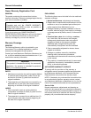
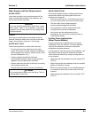
For United Kingdom Only
As the colors of the wires in the mains lead of the appliance may not correspond with the colored markings
identifying the terminals in your plug, proceed as follows:
• The wire which is colored green and yellow
must be connected to the terminal in the plug which is marked with
the letter E or by the earth ground symbol or colored green or green and yellow.
• The wire colored blue
must be connected to the terminal which is marked with the letter N or colored black.
• The wire colored brown
must be connected to the terminal which is marked with the letter L or colored red.


