11
THE TUBE BOARDS
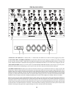
The left tube board takes the mix busses through the 1K MIX GAIN pots, then a 7:1 step-up
transformer. The left signal is amplified by a 25db tube voltage amp/line driver and the right signal
is sent to the right tube board. The voltage amp is a paralleled (for low noise) 12AT7wa direct
coupled into a White Follower line driver which uses a 6044. It is AC coupled with a 30 uF
audiophile grade Multi-cap into the 1/4" Unbalanced Mix Output and a Manley 9811 transformer for
the Balanced XLR Mix Output. A tertiary winding on the 9811 is used for negative feedback
through a trim pot for gain adjustment (located near the top of the board between the tubes). This
circuit is virtually identical to the tube stages used in the Massive Passive and produces +37 dBu
levels ! This stage is quite similar to a Mic Pre with moderate gains.
The left board also distributes most of the power supply busses including the +/- 24 volt, 12 volt led/
relay supply and the 48 Volt phantom supply. There are balanced line receivers for the left EXT
input, and left TAPE input, plus the MONO combining circuit and AUX Line Driver. The AUX buss
amp is a low noise device with 15V regulators next to it. The AUX Gain pot is after the buss amp
and feeds the line driver. This pot can be replaced with a dual pot and jumpers changed to have it
control the EXT levels into the mix buss and monitor switch.
The right tube board has the same tube stage and balanced line recievers for EXT and TAPE, plus
circuitry involved in the monitor section. All monitored signals are sent to a Grayhill gold contact 5
position switch and the selected signals are sent to the VU meter board and the monitor pot. From
the pot, the signal is buffered with heavy duty line drivers and sent to relays for MUTE and Main /
Mini selection on its way to the Monitor jacks.
The right tube board also distributs the 350 volts and 12 volts used for the tube circuits.
The VU board contains the isolation amps for the VU meters and trims for VU calibration plus the
timer used for power-up delay (about 20 seconds). There is also termination for the front panel
power switch, VU illunination, Switch logic, etc.
Removing these boards is similar to removing a channel module. Removing the right tube board is
neccessary in order to remove the left board due to the physical size of some of the parts. Extra care
is required because capacitors can hold a charge long after power is disconnected and with tubes the
stored charge can be 350 volts. Let them discharge! Replacing a tube should not require removing
the boards, just the top cover.
Removal of the tube boards is accomplished by:
1) Unscrewing and sliding back the top & bottom perforated covers.
2) Pulling up and off the white AMP PSU connector and IDC ribbon connector at the bottom of
theleft tube board.
3) Removing the3 hex head 4-40 screws that hold the black engraved front panel.
4) Remove the 4 knobs and 4 nuts that mount the pots and rotary switch.
4) Pull the panel forward away from the two boards.
6) Removing the 8 plastic nuts from the 1/4" jacks and the 8 black 4-40 screws from the XLR jacks
7) Pull the right board forward and out. If a ribbon connector is removed, note its location and
orientation. The left board can now be pulled gently out.


