


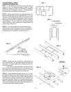

SHUTTER INSTALLATION
STEP 10 — Unpack Model A3024 shutter and read instruc-
tions included. Note that the first part of the shutter instruc-
tions refer to cutting the shutter hole, which you have already
done, and so they may be disregarded. Follow the remaining
instructions to adjust springs so that shutters open and close
freely. (See Fig. 8.)
STEP 11 — Mount shutter to joists directly below fan opening
with wood screws provided. Note sheet rock must be cover-
ing center joist before shutter is installed. Again, make sure
both sides of shutter open and close freely. (See Fig. 9.)
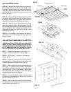
STEP 12 — Return to attic and attach side panels to fan as
shown using remaining short screws and washers. (See Fig.
10.) Bottom of panels should rest upon ceiling. Bend flaps on
ends of panels back when inserting panels between joists.
These flaps will then spring back to seal off any space
between panel and joist.
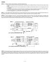
STEP 13 — Fan installation is now complete. With control in
“OFF” position turn on 120V power supply to fan. Test run fan
through all speeds.
WALL INSTALLATION MODEL 3130 SHUTTER
THIS INSTALLATION IS TO BE USED ONLY IN AN ATTIC
GABLE OR WALL WHICH FACES AN UNOCCUPIED
AREA, AN AREA NOT READILY ACCESSIBLE TO PEO-
PLE OR ANIMALS! DO NOT USE THIS INSTALLATION IN
AN ATTIC WITH ANY TYPE OF LOOSE INSULATION.
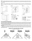
STEP 1 — Construct wood frame as shown in Figs. 11 &
12. Use 2 x 8 framing lumber and 2 x 2 furring strips.
STEP 2 — Drill (4) holes
1
⁄4” in diameter in fan housing as
shown in Fig. 13.
STEP 3 — Position fan in frame and secure with (4) wood or
lag screws (#12 x 1
1
⁄2” preferred) through holes drilled in Step
2. Note 3
3
⁄4” dimension from edge of frame. (Fig. 14)
STEP 4 — Secure Model 3130 shutter with (8) wood or lag
screws (#12 x 1” preferred) through holes in shutter frame.
Shutter should be positioned so that louvers swing outward
and upward. See Fig. 15. Check shutter to make sure it
opens and closes freely. Also check to make sure there is
clearance between shutter and fan blade.
STEP 5 — To mount this attic fan in gable or wall, a box must
be framed into wall construction as shown in Fig. 16. Make
opening in outside wall 37” x 37”.
STEP 6 — Insert frame containing fan and shutter assembly
into opening with outside surface of shutter frame flush with
outside surface of wall. See Fig. 16.
FIG. 10
— 5 —
FIG. 11
FIG. 8
CONNECTOR
SPRING ATTACHED
SPRING HOLDER
LOCKING
SCREW
SPRING SHOWN
UNATTACHED
FIG. 9