


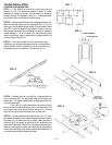
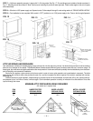

SECURE UNIT IN PLACE
WITH 2” X 2” FURRING
STRIPS INSIDE
FIG. 15
FIG. 14
— 6 —
FIG. 16
FIG. 17
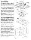
DOUBLE 2 X 6
HEADER
FRAME HOLE AT
37” X 37”
2 X 4 FRAMING
FIG. 12
FIG. 13
STEP 7 — Nail frame assembly securely in place with 2 x 2 furring strips. See Fig. 17. Put moulding around outside of shutter as shown in
Fig. 17. Moulding should be at least 4” wide. Caulk around moulding to provide a water-tight seal. Check shutter again to be sure it opens
and closes freely.
STEP 8 — Wire fan to 120V power supply and 3-speed control. Follow steps 6 through 9 under wiring section of “CEILING INSTALLATION.”
STEP 9 — Fan installation is now complete. With control in “OFF” position turn on 120V power supply to fan. Test run fan through all speeds.
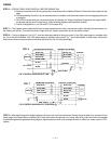
MINIMUM ATTIC DISCHARGE AREAS REQUIRED
(All areas are in square feet)
FAN UNRESTRICTED* WOOD LOUVER* METAL LOUVER*
SIZE OPENING REQD. OPENING REQD. OPENING REQD.
24” 8.5 19.2 15
ATTIC AIR INTAKE AND DISCHARGE
Your wholehouse ventilator will be discharging a large volume of air into the attic every minute. It is obvious that provisions must be made to
allow this air to escape to the outside. The sketches below illustrate several different types of exhaust vents that are in common usage. Of
these types, the under-eave and gable methods are the most prevalent. Under-eave exhaust is probably the most satisfactory from the stand-
point of simplicity and economical installation.
Each size fan requires a given amount of minimum outlet in order to insure quiet operation and unrestricted air movement. The table
below shows the minimum area to be provided for each fan, and the increased size that is required if the outlet is restricted with louvres,
screening, etc.
Sufficient outlet air is most important. Unless enough is provided, the fan will be overloaded, and the motor will run hot, causing the ther-
mal protector to turn it off. When it cools, it will start again. Such intermittent operation is usually an indication of too little outlet air or too little
input air through the house.
B (Ft.)
B (Ft.)
B (Ft.)
A (Ft.)
A (Ft.)
(1/2 A x B = AREA Sq. Ft.)
GABLE EXHAUST
A (Ft.)
(A x B = AREA Sq. Ft.)
GABLE EXHAUST
(A X B = AREA Sq. Ft.)
EAVE
EXHAUST
SECURE UNIT IN PLACE
OUTSIDE WITH MOULDING