


Compact Refrigerators and Freezers Service and Installation Manual
For customer service, call (888) 732-2446 Fax (800) 669-0619, www.mccallrefrigeration.com
4
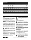
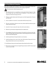
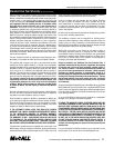
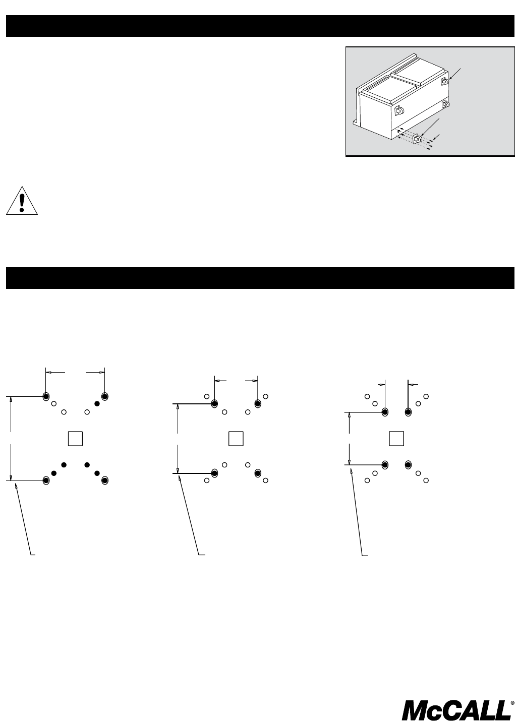
Carefully place the unit on its back (see illustration at right).
Remove legs by unscrewing them in a counter clockwise direction.
Located on each end of the compressor channel are 4 hex head screws, for a total of
8 screws. Remove them. 8 additional screws are provided with your casters.
Place a locking plate caster over one of the front holes, matching the 4 mounting
holes to the pre-drilled holes in the underside of the unit. Insert 4 hex head screws
and tighten. Repeat with the other locking front casters.
Repeat step 4 with the non-locking casters in the rear of the unit.
Carefully lift the unit upright.
After installing casters, the unit must stand upright for twenty-four (24)
hours before being powered up to assure oil return to the compressor
sump.
1.
2.
3.
4.
5.
6.
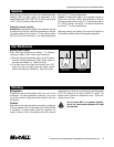
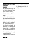
Plate Casters
W/Locks
Plate Casters
W/O Locks
#14 x .75" Hex Head
Screws #932-1116
Plate caster installation, 400 & 4000 Series.
Caster Installation
WARNING
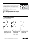
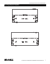
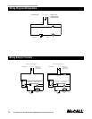
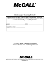
Caster/Leg Mounting Detail
2”, 3” and 5” Caster and Leg Mounting Detail
A universal bolt hole pattern is provided on the bottom of the cabinet. It will accommodate any leg or caster. Simply line up the plate
holes with the corresponding cabinet holes.
2.38”
3.40”
1.75”
2.82”
0.94”
2.14”
NOTE:
If hole pattern on caster/leg
matches the one above mount
in inner set of holes.
2” Caster - 3234148
NOTE:
If hole pattern on caster/leg
matches the one above mount
in middle set of holes.
3” Caster - 3234024
5” Caster - 3234161
NOTE:
If hole pattern on caster/
leg matches the one above
mount in outer set of holes.
6” Leg - 3234569