


8
McCall Series I Reach-In Manual
Location
Cabinets represented in this manual are intended for indoor use
only. Be sure the location chosen has a floor strong enough to
support the total weight of the cabinet, 1000 pounds (450 kg)
per door section. Reinforce the floor if necessary to provide for
maximum loading. For the most efficient operation, be sure to
provide good air circulation inside and out. The location should
be selected so that the power cord can be connected without
any extensions.
Inside Unit
Take care not to block airflow to the fans or heating elements
and allow space along the front, back and sides.
Outside Unit
Be sure that the unit has access to ample air; avoid hot corners and
locations near stoves and ovens. Provide a minimum clearance
of 12” (30cm) above the unit that is open to the front.
Door Removal
The doors can be removed during installation if necessary.
Remove the door by opening the door to 90˚, lift it up and ease
it out of the hinge brackets
Leg, Caster, Utility Base Installation
Some cabinets may weigh over 1000 pounds (450
kg). Use a lifting device capable of supporting the
unit when removing skid or installing legs, casters
or utility base.
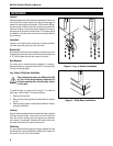
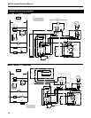
To install the legs, or casters refer to Figure 1. To install the
utility base, refer to Figure 2. Proceed as follows:
Remove unit from skid.
Raise unit to access leg/caster mounting holes on bottom
of unit.
Attach the legs, casters or utility base to bottom of cabinet
using hex head bolts.
Leveling
After the cabinet has been placed in the desired location, cabinets
with legs must be leveled. Level units from front to back and
from side to side. Leveling will insure proper door operation
and removal of condensate. Cabinets with casters must have
the caster brake set so the cabinet cannot move.
Stabilizing
It is very important that all legs are properly adjusted to keep
the cabinet level, evenly distribute the weight and to make sure
the unit will not rock, lean or be unstable.
1.
2.
3.
Figure 1. Leg or Caster Installation
Figure 2. Utility Base Installation
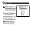
WARNING
Installation