


RT-2VSE/VSHO Service Manual
2
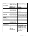
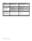
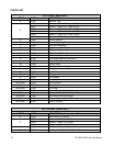
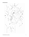
PARTS REPLACEMENT
(For models: RT-2VSE & RT2-VSHO)
A
–
CASE REMOVAL
1. Remove reflector tray, toast pan and delivery
chute.
2. Remove the 2 screws along the front trim panel
and remove.
3. Remove left front panel.
4. Remove the 4 screws holding control panel to
unit and carefully pull panel towards you with all
wires intact. Slide control panel towards center
of unit.
5. With hands on each side of case, pull forward to
remove.
B – CASE REPLACEMENT
1. Slide case over unit making sure tabs on the
sides and top of case fit into grooves on back of
unit.
2. Carefully replace control panel.
3. Replace left front panel and front trim panel.
4. Replace reflector tray, toast pan and delivery
chute.
C – ON/OFF (MAIN POWER) SWITCH
1. With control panel removed, remove the 2
slotted screws holding the ON/OFF switch to the
control panel.
2. Disconnect wires and remove switch.
3. Install new switch from rear of panel and
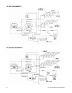
reconnect wires. (Refer to appropriate wiring
diagram)
D – CONVEYOR ON/OFF SWITCH
1. With the control panel removed, disconnect
wires to switch noting proper orientation.
2. Remove bezel from front of panel and push
switch through back of panel.
3. Insert new switch from back of panel. NOTE:
Be sure terminals are in correct position.
4. Attach bezel on front of panel and tighten.
5. Re-attach wires to switch. (Refer to appropriate
wiring diagram.)
E
–
INFINITE CONTROL SWITCH
1. With control panel removed, remove the infinite
control knob to gain access to the 2 slotted
screws that hold the control to the unit. Remove
these 2 screws.
2. Disconnect wires from infinite switch terminals.
3. Install new switch from back of panel and reattach
wires. (Refer to appropriate wiring diagram).
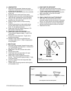
F – BUN-TOAST SWITCH
1. Remove control panel.
2. The bun-toast switch is held in place by a spring
clip on the back of the control panel. Pry this clip
from the 2 switch tabs and remove.
3. Squeeze the spring clip together and push it
through the front of the control panel.
4. Disconnect wires from switch.
5. Install new switch from front of panel. (NOTE:
New switch has spring clip already attached.)
6. Re-attach wires to switch. (Refer to appropriate
wiring diagram.)
G – SPEED CONTROL
1. With control panel removed, loosen set screws on
speed control knob and remove.
2. Remove retaining nut that holds speed control in
place and remove from back of panel.
3. Disconnect motor lead and on/off lead from speed
control.
4. Reverse this procedure to install new assembly.
(Refer to appropriate wiring diagram.)
!
WARNING: Disconnect unit from power source before attempting any service.