RT-2VSE/VSHO Service Manual
4
L
–
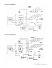
CONVEYOR CHAIN
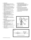
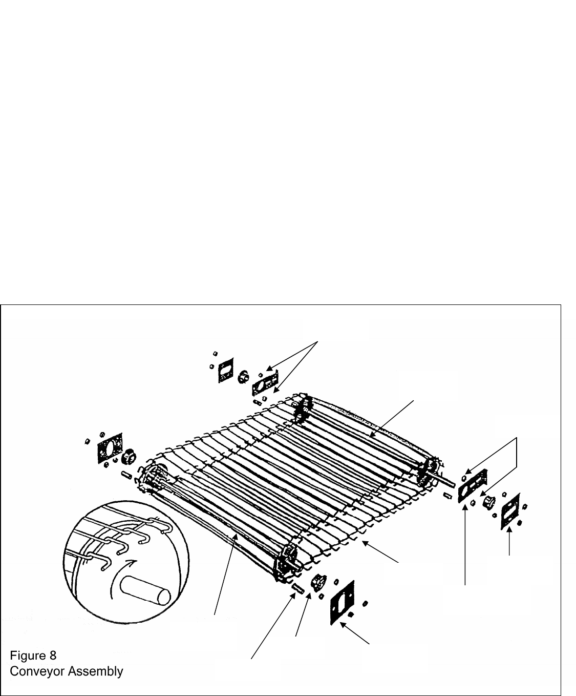
Figure 8
1. With outer case removed, loosen motor
mounting bracket retaining bolts on underside of
unit and slide motor to the left.
2. Loosen rear shaft adjusting bracket nuts and
bearing retaining bracket nuts on both sides of
unit.
3. Slide rear conveyor shaft forward to loosen the
tension.
4. Separate the chain at any link and slide out from
front of unit.
5. Before installing new chain, check for proper
orientation (see Figure 8) and correct number of
links.
6. Starting at front of unit, slide chain under front
shaft and push towards rear of unit. Bring chain
up and over rear shaft assembly and pull
towards front. Connect links. CAUTION: MAKE
SURE CHAIN IS NOT INSTALLED AT AN
ANGLE.
7. Push back on rear shaft assembly until excess
slack is removed from chain. Holding tension,
tighten both the rear shaft adjusting brackets
and bearing retaining brackets on both sides of
unit.
8. Check for proper tension. There should be
approximately ” to ¾” space between the
conveyor chain and the ledge on the inside of
the unit cavity.
9. Slide motor to the right to tighten drive chain
tension. There should be approximately ¼” play
in the drive chain.
10. Tighten motor mounting bracket retaining bolts
on underside of unit.
Spacer Nuts
Rear Shaft
Assembly
Spacer Nuts
Bearing
Retainer
Tension Adjusting
Bracket
Wire Belt
Bearing
Retainer
Bearing
Front Spacer
Front Shaft
Assembly


