2
WARNING: DISCONNECT UNIT FROM POWER SOURCE BEFORE ATTEMPTING ANY SERVICE PROCEDURE
General Information: The units covered in this Parts
and Service Manual, SG-18, SG-22 and SG-34, are
engineered for efficient, dependable service throughout
the years. Like any piece of fine equipment with moving
parts and broad temperature ranges, physical ware
takes its toll. When this happens, the information found
in this manual will prove most helpful. Although the
instructions are easy to follow, the work should be
carried out by a qualified Service Technician.
General Instructions: The following instructions refer
to all models in the SG Series hot dog grills. The SG-18
model will vary slightly due to having only one motor,
but the parts replace instructions remain essentially the
same. The right and left side of the unit is determined
by facing the front (control switch) side of the grill. The
left side switch controls the front 5 (#1 thru #5) rollers
on the grill. The right side switch controls the rear 5 (#6
thru #10) rollers.
A Panel Removal:
1. All parts replacement procedures will require the
removal of one or both side panels and/or the
bottom panel.
2. To remove either side panel; remove the 8 sheet
metal screws.
3. To remove the bottom panel; tilt the grill up from the
front and rest on the back of the unit. Remove the 6
sheet metal screws. (SG-34 model has 10 screws)
B Control Switch Replacement:
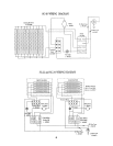
(Figure 1, 4 & 5)
1. Remove bottom panel. (Section A)
2. Remove the 2 slotted screws and spacers securing
the switch to the front panel. Note proper orienta-
tion of spacers.
3. Disconnect wire leads from switch terminals.
4. Remove switch from underside of unit.
5. Insert new switch from underside of unit and secure
with the 2 slotted screws and spacers.
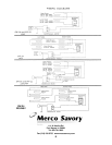
6. Re-attach wire leads to switch terminals. (Refer to
appropriate wiring diagram)
C Power Indicator Light Replace-
ment:
(Figure 1, 4 & 5)
1. Remove bottom panel. (Section A)
2. Disconnect the wire leads from back of light.
3. Press spring loaded tabs on back of light and push
through front of panel.
4. Insert new light from front of unit and snap into place.
5. Re-attach wire leads to light terminals. (Refer to
appropriate wiring diagram)
D Terminal Block Replacement:
(Figure 4 & 5)
1. Remove bottom panel and appropriate side panel.
(Section A)
2. Remove the 2 screws and nuts securing the terminal
block to the unit.
3. Disconnect wire leads from terminal block, noting
proper orientation.
4. Secure new terminal block to unit with the 2 screws and
nuts.
5. Re-attach wire leads to terminal block. (Refer to
appropriate wiring diagram)
E Motor & Motor Sprocket Replace-
ment:
(Figure 2, 3, 4 & 4)
1. Remove bottom panel and appropriate side panel.
(Section A)
2. Loosen the 4 motor mounting nuts securing the motor
to the unit and slide motor to loosen drive chain tension.
Slip drive chain off motor sprocket (and idler sprocket
on SG-18 models).
3. Disconnect wire leads from motor terminals.
4. Remove the loosened motor mounting nuts and remove
motor.
5. Before installing new motor, transfer the motor fan and
sprocket from the old motor to the ne motor. Note
proper orientation of fan blades. To remove the
motor sprocket from the motor shaft, loosen the set
screw in the sprocket with an Allen wrench, and slip
sprocket off shaft. Note proper orientation of set
screws (on the flat portion of the motor shaft) and
the sprocket.
6. Secure new motor (with fan and sprocket in place) to
unit with the 4 motor mounting nuts. Do NOT tighten
nuts.
7. Place drive chain around motor sprocket (and over idler
sprocket on SG-18 models).
8. Slide motor to tighten drive chain tension and tighten
the 4 motor mounting nuts.
9. Re-attach wire leads to motor terminals. (Refer to
appropriate wiring diagrams)


