7
ENGLISH
SECTION 2 - INSTALLATION
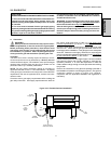
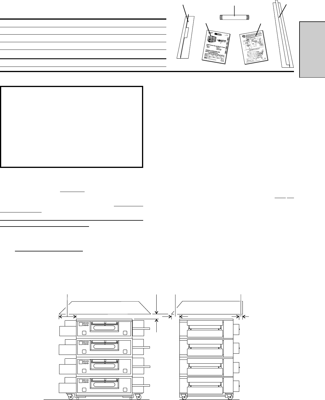
458mm minimum
(Typical - both
ends of oven)
76mm
minimum
203mm
minimum
51mm
minimum
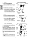
Fig. 2-3 - Ventilation System
43
2
15
CODES SUPERSEDE THE RECOMMENDATIONS SHOWN IN
THIS MANUAL.
The rate of air flow exhausted through the ventilation system
may vary depending on the oven configuration and hood design.
Consult the hood manufacturer or ventilation engineer for these
specifications.
To avoid a negative pressure condition in the kitchen area,
return air must be brought back to replenish the air that was
exhausted. A negative pressure in the kitchen can cause heat-
related problems to the oven components as if there were no
ventilation at all. The best method of supplying return air is
through the heating, ventilation and air conditioning (HVAC)
system. Through the HVAC system, the air can be temperature-
controlled for summer and winter. Return air can also be
brought in directly from outside the building, but detrimental
effects can result from extreme seasonal hot and cold
temperatures from the outdoors.
NOTE: Return air from the mechanically driven system
must not
blow at the opening of the baking chamber. Poor oven baking
performance will result.
C. Other ventilation concerns
Special locations, conditions, or problems may require the
services of a ventilation engineer or specialist.
Inadequate ventilation can inhibit oven performance.
It is recommended that the ventilation system and duct
work be checked at prevailing intervals as specified by the
hood manufacturer and/or HVAC engineer or specialist.
A. Requirements
CAUTION
Gas oven installations
REQUIRE a mechanically driven
ventilation system with electrical exhaust air sensing control.
A mechanically driven ventilation system is
STRONGLY
RECOMMENDED for electric oven installations.
PROPER VENTILATION OF THE OVEN IS THE
RESPONSIBILITY OF THE OWNER.
B. Recommendations
NOTE THAT THE HOOD DIMENSIONS SHOWN IN FIGURE 2-
3 ARE
RECOMMENDATIONS ONLY. LOCAL, NATIONAL, AND
INTERNATIONAL CODES MUST BE FOLLOWED WHEN
INSTALLING THE VENTILATION SYSTEM. ANY APPLICABLE
III. VENTILATION SYSTEM
IMPORTA NT
Where national or local codes require the
installation of fire suppression equipment or
other supplementary equipment, DO NOT mount
the equipment directly to the oven.
MOUNTING SUCH EQUIPMENT ON THE OVEN MAY:
VOID AGENCY CERTIFICATIONS
RESTRICT SERVICE ACCESS
LEAD TO INCREASED SERVICE EXPENSES
FOR THE OWNER
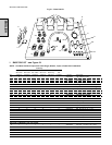
Fig. 2-2 - Installation Kit
II. INSTALLATION KIT - see Figure 2-2
NOTE: One Installation Kit is required for each oven cavity.
Item Qty. Part No. Description
1 1 35900-0148 Conveyor Rear Stop
2 1 35000-1103 Conveyor End Stop
3 1 47008 Owner's Operating & Installation Manual
4 1 1002040 Authorized Service Agency Listing
ADDITIONAL COMPONENTS FOR PS555G AND PS570G GAS OVENS:
5 1 33120-0053 Gas Pipe Nipple


