


SECTION 2
INSTALLATION
13
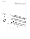
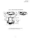
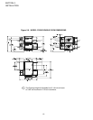
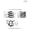
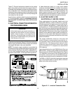
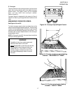
These ‘C’ Channel brackets are installed in the vertical
plane using existing screws (Item 6) to support these ‘C’
Channels using the upper and lower Key Hole openings in
the ‘C’ Channels. The ‘C’ Channels are identical and once
installed will allow ample amounts of air through the cooling
fan mounted on the rear side of the ovem by keeping the
oven away from the rear wall.
If you have any questions about how to mount these two
‘C’ Channel brackets, kindly phone Middleby Technical
Services at 847-741-3300. Press 3, then 5 for Technical
Support.
III. ELECTRICAL CONNECTION INFORMATION
FOR PS520-SERIES OVENS.
WARNING
Authorized supplier personnel normally ac-
complish the connections for the ventilation
system, electric supply, as arranged by the
customer. Following these connections, the
factory-authorized installer can perform the
initial startup of the oven.
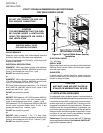
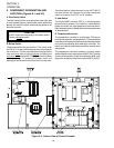
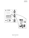
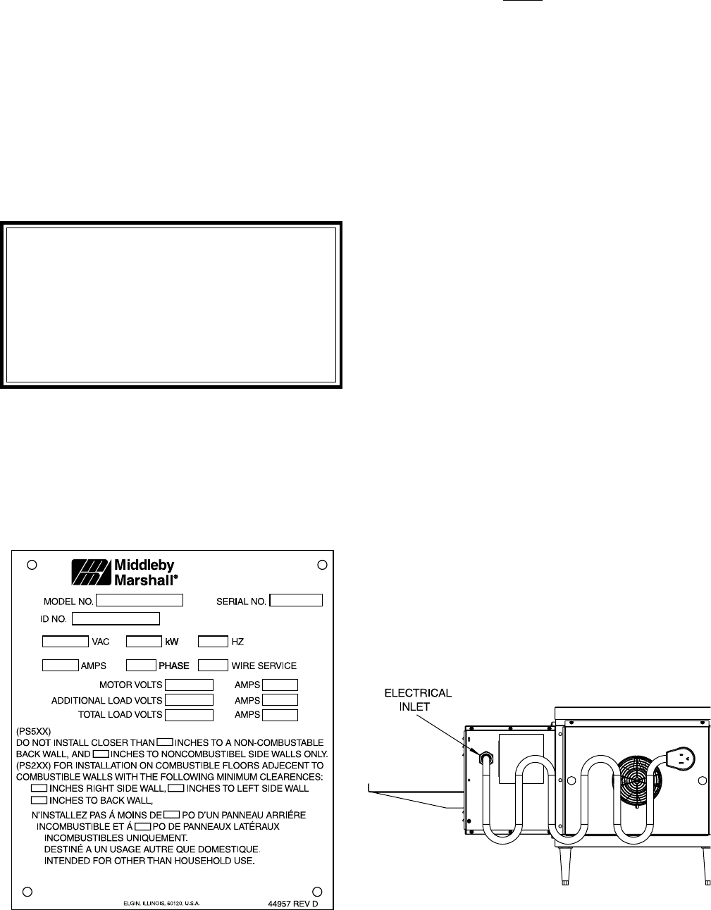
Check the oven data plate (Figure 2-10) before making any
electric supply connections. Electric supply connections
must agree with data on the oven data plate.
NOTE: The electric supply installation must satisfy the
requirements of the appropriate statutory authority, such
as the National Electrical Code (NEC), ANSI/NFPA70,
(U.S.A.); the Canadian Electrical Code, CSA C22.2; the
Australian Code AG601; or other applicable regulations.
A fused disconnect switch or a main circuit breaker
(customer furnished)
MUST be installed in the electric
supply line for each oven; it is recommended that this
switch/ circuit breaker have lockout/tagout capability. The
electric supply connection must meet all national and
local electrical code requirements. Copper is the recom-
mended material for the electrical supply conductors.
IV. ELECTRIC SUPPLY FOR
ELECTRICALLY HEATED OVENS
Power requirements for electrically heated ovens are
usually 208 - 240VAC, 1-phase, 3-wire (2 ‘hot’, 1 ground),
although ovens built for export can have power require-
ments of 380VAC and 480VAC. (These ovens have a
4-wire system.) A 1.5″ (38mm) diameter cutout/hole in the
back of the machiney compartment provides access for
the electrical supply connections on 380V and 480V units.
208V and 240V units have a cord and plug. Using flexible
cable(s) for the electrical power supply conductors re-
quires a 2″ (51mm) strain-relief fitting (not furnished) to
enable safe access to the terminal block from which oven
power is distributed.
The supply conductors must be of the size and
material (copper) recommended to provide the cur-
rent required; (refer to the data plate for the ampere
specifications). The electric current rating for each
conductor supplying a PS520-Series Oven ranges
from a minimum of 17.3 amperes to a maximum of
39.9 amperes.
Typical specifications for each PS520-Series Oven are
208V or 240V, 1-phase, 3-wire, 8.3kW; this oven requires
50-ampere service. A PS520-Series Double Oven (Figure
1-2) installation would require two 50-ampere service
connections, one for each oven; the 8.3kW power con-
sumption also doubles for such an installation to 16.6kW.
The 208V or 240VAC electrically heated oven uses two
legs of the supplied power to provide 208V or 240VAC
power for the oven control circuitry.
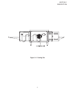
Figure 2-11. Junction Connection BoxFigure 2-10. Typical Electric Oven Data Plate