5
ENGLISH
SECTION 1 - DESCRIPTION
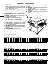
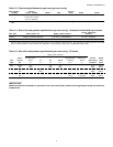
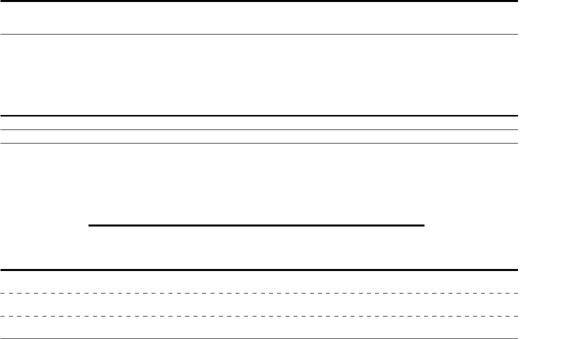
Table 1-3: Electrical specifications for gas ovens (per oven cavity)
Main Blower Control Current
Voltage Circuit Voltage Phase Freq. Draw Poles Wires
208/240V 120V conv. speed control 1 Ph 50/60 Hz 6A * 2 Pole 3 Wire (2 hot, 1 gnd)
& drive motor; all others
as per line (208/240V)
* The current draw shown above is an average value for normal operation. The initial amperage draw on oven startup may exceed the listed
value.
IMPORTANT
Additional electrical information is provided on the oven's serial plate, and on the wiring diagram inside the machinery
compartment.
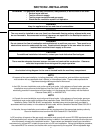
Table 1-5: Gas orifice and pressure specifications (per oven cavity) - CE ovens
Supply (Inlet) Pressure
IT,PT,ES,SE,
Main UK,CH,IT,AT, SE,CH,AT,DK, BE,IE,IT,PT, Orifice Rated
Gas Orifice DK,FI NL DE BE,FR FI,DE,NL ES,UK (Manifold) Heat
Type dia.
I
2H
I
2L
I
2E
I
2E+
I
3B/P
I
3+
Pressure Input
G20 2.3749 20 -- 20 20 -- -- 11.21 22.36
mm mbar mbar mbar mbar kW-hr.
G25 2.3749 -- 25 -- -- -- -- 16.19 22.36
mm mbar mbar kW-hr.
G30 1.3970 -- -- -- -- 29 or 50 28-30, 37 26.2 22.59
mm mbar or 50 mbar mbar kW-hr.
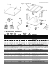
Table 1-4: Gas orifice and pressure specifications (per oven cavity) - Domestic and standard export ovens
Orifice (Manifold)
Gas Type Main Orifice I.D. Supply (Inlet) Pressure Pressure
Natural 0.0935” (2.3749mm, #42 drill) 6-12” W.C. (14.9-29.9mbar) * 4.0” W.C. (9.93mbar)
Propane 0.081” (2.0574mm, #46 drill) 11-14” W.C. (27.4-34.9mbar) * 10.5” W.C. (26.15mbar)
* The gas supply pressures and orifice sizes shown are for ovens installed in North America. The required gas supply pressures and orifice
sizes of ovens installed in other locations are dependent on the local gas type and on all applicable local codes.


