20
SECTION 2
INSTALLATION
V. GAS SUPPLY FOR GAS HEATED
OVENS
WARNING
During gas line pressure testing, observe the
following precautions:
1. The oven
and its individual shutoff valve
MUST be disconnected from the gas supply
piping system during any pressure testing of
that system at test pressures in excess of
1/2 psig (3.45kPa).
2. The oven MUST be isolated from the gas
supply piping system, by closing its individual
shutoff valve, during any pressure testing of that
system at test pressures equal to, or less than,
1/2 psig (3.45kPa).
3. If incoming gas line pressure exceeds
14″w.c. (35mbar), a separate regulator MUST be
installed in the line on the inlet side of the safety
valve for the oven.
CAUTION
To prevent damaging the control valve regulator
of the oven during initial turn-on of gas, the
individual shutoff valve MUST be opened
very
slowly.
After initial turn-on of gas, the individual
shutoff valve should remain open except during
gas line pressure testing (refer to the preceding
WARNING) and during necessary servicing and
maintenance procedures.
Check the oven data plate (Figure 2-11) before making any
gas supply line connections. The type of gas (natural or
propane) being supplied to the oven must agree with data
on the oven data plate.
Certain safety code requirements exist for the installation
of gas ovens; refer to the beginning of Section 2 for a list
of the installation standards. In addition, because a
PS540-Series oven is equipped with casters for accessi-
bility during servicing, the gas line connection shall be
made with a connector that complies with the Standard for
Connectors for Movable Gas Appliances, ANSI Z21.69 (in
U.S.A.), or, if applicable, Connectors for Movable Gas
Appliances, CAN/CGA-6.16 (in Canada), as well as a
quick-disconnect device that complies with the Standard
for Quick-Disconnect Devices for Use With Gas Fuel,
ANSI Z21.41 (in U.S.A.), or, if applicable, Quick-Discon-
nect Devices for Use With Gas Fuel, CAN6.9 (in Canada).
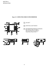
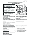
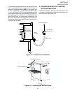
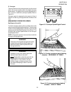
One gas line connection method is shown in Figure 2-13;
however, the preceding requirements must be satisfied.
The 90-degree elbow and the union shown in Figure 2-13
are not furnished; however, the flexible gas line is part of
the installation kit.
On an oven equipped with casters, a cable restraint
assembly must be installed to limit the movement of the
appliance, without depending on the connector and quick-
disconnect device or its associated gas line installation.
The location where the Cable Restraint Assembly is to be
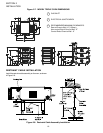
attached to the oven is illustrated in Figure 2-8.
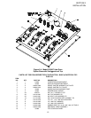
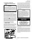
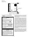
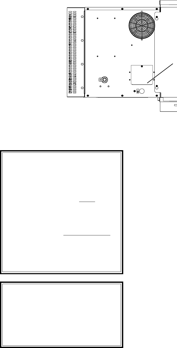
Figure 2-12. Junction Connection Box
Electrical Junction
Cover Plate


