


8
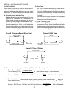
B. PS360-series ovens
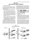
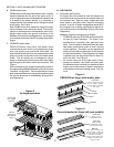
PS360-series ovens feature two blower motors. A blower
wheel is fastened onto the end of the motor shaft. In
order to adjust the amount and speed of heated air that
is directed by the blower wheels, it is necessary to
change the size of the wheels and/or change the speed
of the motor. See Figure 1.
Each PS360-series oven model has a specific combi-
nation of blower motor and blower wheel. Field modifi-
cations to these approved combinations are not per-
mitted unless under the specific directions of the
Middleby Technical Service Department. Any changes
to convection air delivery MUST be made using the air
fingers.
C. PS555/570-series ovens
PS555/570-series ovens have one blower motor
mounted inside each of the end compartments of the
oven, with a pulley on the end of the motor shaft. The
oven has two blower wheels; a belt connects each motor
pulley to a pulley on the end of one of the blower wheel
shafts. The air velocity can be changed by using a
larger or smaller pulley on the motor shaft, and chang-
ing the length of the belt to match the new pulley. See
Figure 1.
Some customers have a specific belt/pulley combina-
tion approved by Middleby Marshall, while others use a
standard configuration. Field modifications to these
approved combinations are not permitted unless under
the specific directions of the Middleby Technical Ser-
vice Department.
SECTION 2 - AIR FLOW AND HEAT TRANSFER
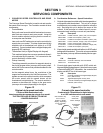
III. AIR FINGERS
A. Description and Function
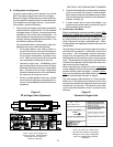
Air fingers direct the heated air from the blowers into
vertical jets that are directed at the top and bottom of
the conveyor belt. Each air finger configuration has
been tested to optimally cook a specific customers
product. As a rule, air finger configurations should NOT
be changed from customer specifications without di-
rect instructions from the Middleby Technical Services
Department.
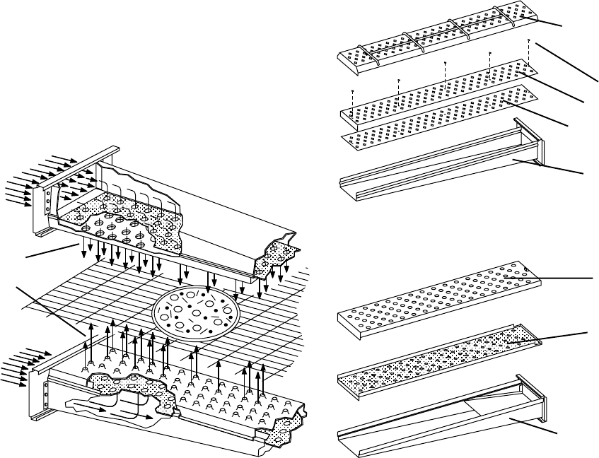
Middleby uses two main types of air fingers:
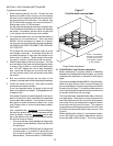
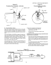
PS300/350 and early PS310/360 ovens used a shut-
ter-type air finger assembly. The finger is as-
sembled from a manifold, inner plate and outer
plate. The inner plate is assembled from two sepa-
rate plates, each with a series of holes, that are
riveted together. The plates can be repositioned
relative to each other to restrict the air flow through
the holes as necessary. These fingers are no longer
in general use, but may still be found in older ov-
ens in the field. See Figure 3.
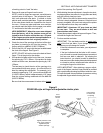
All current ovens use an air finger which is com-
posed of a manifold, inner plate, and outer plate.
No adjustments are necessary or possible to these
fingers, but a wide variety of styles is available to
meet different customers baking needs. See Fig-
ure 4.
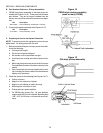
Figure 2
Air finger operation
Hot air flow
from blower
wheel(s)
Vertical
columns of
high-velocity
hot air
Figure 3
PS300/350 air finger with shutter plate
Figure 4
Current standard air finger (all oven models)
Outer plate
Lower air fingers have wire
rack as shown to prevent
conveyor belt from rubbing
on outer plate.
Inner plate
Shutter
Manifold
Rivets
Manifold
Width varies to match inner
and outer plates. Baffle may
be solid, perforated, partially
perforated, or absent.
Several special shapes are
available to meet specific
customer needs.
Outer plate
Width and hole
configuration varies.
Inner plate
Width and hole
configuration varies.
May have inner dam.