


11
ENGLISH
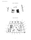
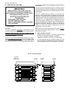
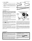
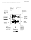
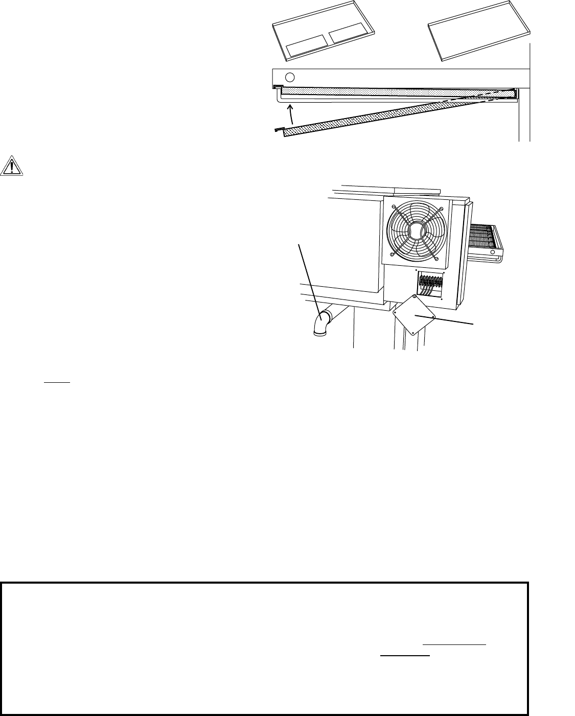
Figure 2-12 - Crumb trays
Crumb trays
with slots
Lower oven
cavity ONLY
All upper oven
cavities
Crumb trays
without slots
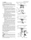
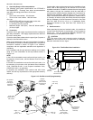
Figure 2-13 - Utility Connection Locations
Electrical
Junction Box
One per oven
cavity
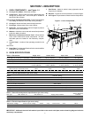
VI. ELECTRICAL SUPPLY
WARNING
Authorized supplier personnel normally accomplish
the connections for the ventilation system, electric supply,
and gas supply, as arranged by the customer. Following
these connections, the factory-authorized installer can
perform the initial startup of the oven.
NOTE: The electric supply installation must satisfy the
requirements of the appropriate statutory authority, such as the
National Electrical Code (NEC), ANSI/NFPA70, (U.S.A.); the
Canadian Electrical Code, CSA C22.2; the Australian Code
AG601; or other applicable regulations.
NOTE: The electric supply connection must meet all national
and local electrical code requirements.
Check the oven serial plate before making any electric supply
connections. Electric supply connections must agree with data
on the oven serial plate.
A fused disconnect switch or a main circuit breaker (customer
furnished) MUST be installed in the electric supply line for each
oven cavity. It is recommended that this switch/circuit breaker
have lockout/tagout capability.
The supply conductors must be of the size and material (cop-
per) recommended. Refer to the wiring diagram inside the
machinery compartment of the oven. Electrical specifications
are also listed on the oven's serial plate.
The oven requires a ground connection to the oven ground
screw located in the electrical junction box. (The box is shown
in Figure 2-13.) If necessary, have the electrician supply the
ground wire. Do NOT use the wiring conduit or other piping for
ground connections!
Gas Inlet
One per Single,
Double, Triple,
or Quad Oven
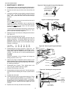
V. FINAL ASSEMBLY
1. Refer to Figure 2-12 to determine the correct locations of
the crumb trays.
2. Install the crumb trays underneath the conveyor as shown
in Figure 2-12. First, place the inside edge of the tray onto
the retainer. Then, swing the outside edge of the tray up and
into place.
3. Press the conveyor end stop and rear stop down over the
edge of the conveyor frame.
All electric supply connections are made via the electrical
junction box on the rear of the oven, shown in Figure 2-13. The
power lines then connect to the oven circuits through safety
switches located inside the machinery compartment and each
blower motor compartment. These switches interrupt electric
power to the oven when the Machinery Compartment Access
Panel is opened, OR when either of the rear shrouds is
removed.
Refer to the wiring diagram inside the machinery compartment
of the oven to determine the correct connections for the electrical
supply lines. Connect the supply as indicated on the wiring
diagram. Be sure to connect the electrical supply ground wire
to the oven ground screw located in the junction box on the rear
of the oven.
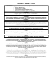
VII. GAS SUPPLY
CAUTION
DURING PRESSURE TESTING NOTE ONE OF THE FOLLOWING:
1. The oven and its individual shutoff valve must be discon-
nected from the gas supply piping system during any
pressure testing of that system at test pressure in excess
of 1/2 psi (3.45 kPa).
2. The oven must be isolated from the gas supply piping
system by closing its individual manual shutoff valve dur-
ing any pressure testing of the gas supply piping system at
test pressure equal to or less than 1/2 psi (3.45 kPa).
3. If incoming pressure is over 14 W.C. (35mbar), a sepa-
rate regulator MUST be installed in the line BEFORE the
individual shutoff valve for the oven.
WARNING: To prevent damage to the control valve regula-
tor during initial turn- on of gas, it is very important to open
the manual shutoff valve very slowly.
After the initial gas turn-on, the manual shutoff valve must
remain open except during pressure testing as outlined in
the above steps or when necessary during service main-
tenance.
SECTION 2 - INSTALLATION