


4
SECTION 1
DESCRIPTION
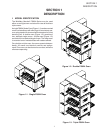
II. COMPONENT FUNCTION (Figure 1-4)
II. COMPONENT FUNCTION
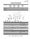
A. Conveyor Motor and Conveyor Belt
The conveyor belt is driven by a variable-speed electric
motor (Figure 1-5) operating through a gear reducer.
The motor speed is controlled by a digital control. The
stainless-steel wire belt can travel in either direction at
variable rates ranging from 30 seconds to 12 minutes; this
is the time that a product can take to pass through
the oven.
B. Blower Fan
The circulation air blower drive motors (2) are located in
the right side control box. The blowers force heated air
through the air fingers. The MAIN / BLOWER switch
must be set to “ON” or “I” for oven warmup and baking.
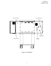
C. Cooling Fan — See Figure 1-5 and Figure 1-6
Cooling fans are located at the rear of each (left and
right) control box. Cooling air is drawn into each control
box and blown across the control components and
circulating blower bearings and exits the oven front and
rear louvers.
IMPORTANT
THE CONTROL BOX DOORS MUST BE
CLOSED WHILE THE OVEN IS HOT OR
HEATING IN ORDER TO KEEP THE
COMPONENTS AND BEARINGS COOL.
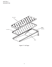
D. Air Fingers - See Figure 1-7
An Air Finger Assembly is made up of three parts:
1. Outer Plate - The Outer Plate is the removable covering
with tapered holes, which direct the air stream onto the
product being baked.
2. Inner Plate -The perforated Inner Plate is vital in forming
the unique air jets. It must be assembled into the manifold
with its holes aligned with the holes of the outer plate.
3. Manifold - The Manifold is the assembly which slides
on tracks into the oven plenum.
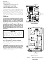
Figure 1-5. Machinery Compartment
Components
Blower Assembly
Right Control Box
#OOLING&AN
"LOWER
-OTOR
Conveyor
Drive Motor