


IV. ASSEMBLY
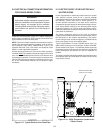
A. Top Panel and Base Pad Assembly
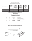
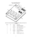
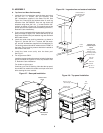
1. Install the four leg extensions onto the base pad using
the 3/8″-16 × 1″ screws, 3/8″ flat washers, and
3/8″ lockwashers supplied in the Base Pad Kit. See
Figure 2-6. Check that the finished sides of each leg
extension face OUTWARDS. One rear leg should be
attached using three 3/8″-16 × 1″ screws and the 3/4″
eyebolt, as shown in Figure 2-6. This eyebolt acts as the
anchor point for the restraint cable assembly (see Part C,
Restraint Cable Installation).
2. If your oven is equipped with the lower shelf, position it in
place as shown in Figure 2-6. Check that the lip on the
shelf faces DOWN. Seal joint between leg and shelf with
NSF listed silicone.
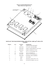
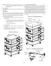
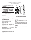
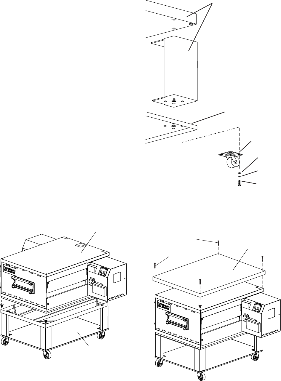
3. Install one caster onto each leg extension, as shown in
Figure 2-7. Use the 3/8″-16 × 1″ screws, 3/8″ flat wash-
ers, and 3/8″ lockwashers supplied in the Installation Kit.
The locking casters should be installed at the FRONT of
the oven. The non-locking casters should be installed at
the REAR of the oven.
4. Install the lower oven cavity onto the base pad.
See Fig 2-7.
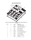
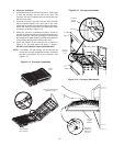
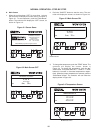
5. For single ovens ONLY:
Install the top panel using the screws included in the base
pad kit, as shown in Figure 2-8. Then, skip ahead to Part
C, Restraint Cable Installation.
For double or triple ovens:
Continue on to Part B, Stacking. Note that the top panel
should NOT be installed for double and triple ovens until
after stacking the oven cavities.
Figure 2-6. Leg extension and casters installation
Figure 2-7. Base pad Installation
Assembled•
base pad
Bottom oven
•
cavity
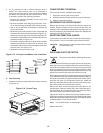
#10-32 × 3/4″
screw length
Top
panel
Figure 2-8. Top panel installation
9
Finished sides of
leg extension face
corner of base
pad
Lower
shelf
Locking casters -
FRONT of oven
Non-locking casters -
REAR of oven
3/8″ flat
washer
3/8″ lock
washer
3/8″-16 × 1″
hex screw
Domestic and
standard export
ovens:
#10-32 × 2-1/2″
screw length