


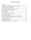
Table of Contents
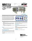
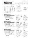
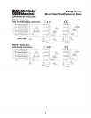
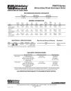
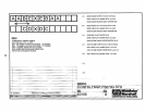
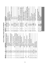
Spec Sheet ...................................................................................................................... 3
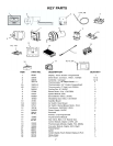
Key Parts ........................................................................................................................ 7
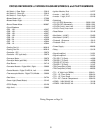
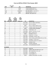
Cross Reference of Wiring Diagram Symbols and Part Number(s) .............................. 8
View of Installation Kit(s) and Base Kit(s) .................................................................... 9
Parts for Installation Kit(s) and Base Kit(s) .................................................................. 10
Standard Finger Conguration and Part Numbers 60188B ........................................... 11
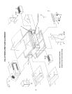
View of Oven Panels, End Plugs and Window ............................................................. 12
Parts for Oven Panels, End Plugs and Window ............................................................ 13
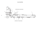
View of Gas Piping ....................................................................................................... 14
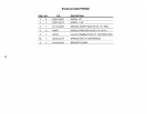
Parts for Gas Piping ...................................................................................................... 15
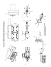
View(s) of Burner/Blower Motor Assembly ................................................................. 16
Parts for Burner/Blower Motor Assembly .................................................................... 17
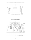
View(s) of Front Control Area(s) .................................................................................. 18
Parts for Front Control Area(s) ..................................................................................... 19
View of Rear Compartment and Blowers (Conveyor Drive End Shown) .................... 20
Parts for Rear Compartment and Blowers (Conveyor Drive End Shown) ................... 21
View of “Single” Belt Conveyor ................................................................................... 22
Parts for “Single” Belt Conveyor .................................................................................. 23
View of “Split” Belt Conveyor ..................................................................................... 24
Parts for “Split” Belt Conveyor .................................................................................... 25
Wiring Diagram, G208-240, 50/60Hz, 1 Phase 54745 Rev. I ....................................... 26
2