


11
Installation Instructions
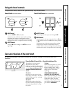
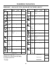
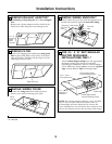
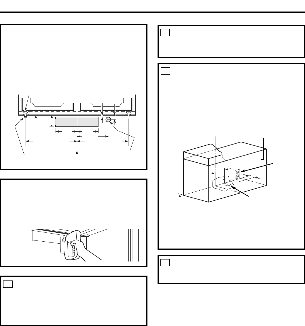
Wood shims
(recessed-bottom cabinets only–shims must be a
minimum of 3/8” thick and cut to fit the width
of the inner recessed cabinet bottom)
Cabinet front
Center line
Electrical access hole
(in wall)
Hood mounting screws (4)
Horizontal duct
access hole
Cabinet
bottom
13¾” (30” hood)
16¾” (36” hood)
1¼”
½”
3¾”
5¼”
5¼”
7¾”
13¾” (30” hood)
16¾” (36” hood)
C.
Outside rear exhaust
(Horizontal duct–3¼
”
x 10
”
Rectangular)
• Use the diagram or the hood as a template and
mark the locations on the cabinet for ductwork,
electrical wiring and keyhole screw slots.
RUN WIRES
Run the electrical wires through the wall or
cabinet according to National Electrical Code
and applicable local codes.
NOTE: DO NOT turn the power on until
installation is complete.
11
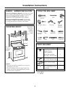
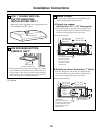
CUT HOLES*
Cut holes at marked locations for duct and electrical
wiring. For the vertical duct, cut out ¾” extra toward
the front of the cabinet so you can move the duct
freely when installing the hood. It may also ease
installation by cutting the hole 10½” instead of 10”.
10
* 1 Ft = 0.3 m
1” = 2.5 cm
SCREW IN PARTWAY
Drive a mounting screw (from the hardware packet)
partway into each center of the narrow neck of the
keyhole slots marked on the cabinet bottom.
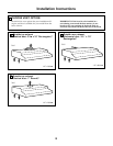
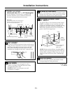
OPTIONAL POWER CORD
KIT JXHC1*
An optional Power Cord Connection Kit, model
JXHC1, is available at extra cost from your GE
supplier for installation using a standard 3-prong,
grounded wall outlet. Follow the Installation
Instructions packed with the kit to connect the
power cord to the range hood.
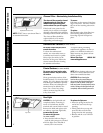
12
13
NOTE: If using optional Power Cord Kit JXHC1,
feed the power cord through the hole in the top
cabinet while raising the hood. Loop any excess
length of cord and tie away with a suitable tape
or tie.
Cabinet
7¾”
3-prong
wall outlet
(if using cord
connection)
1¼”
1¾” dia. clearance hole
for optional power
supply location
C
L
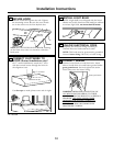
FEED IN WIRES
Lift the hood into position and feed the house
wiring through the wiring knockout.
14