


9
L
N
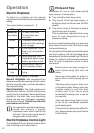
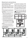
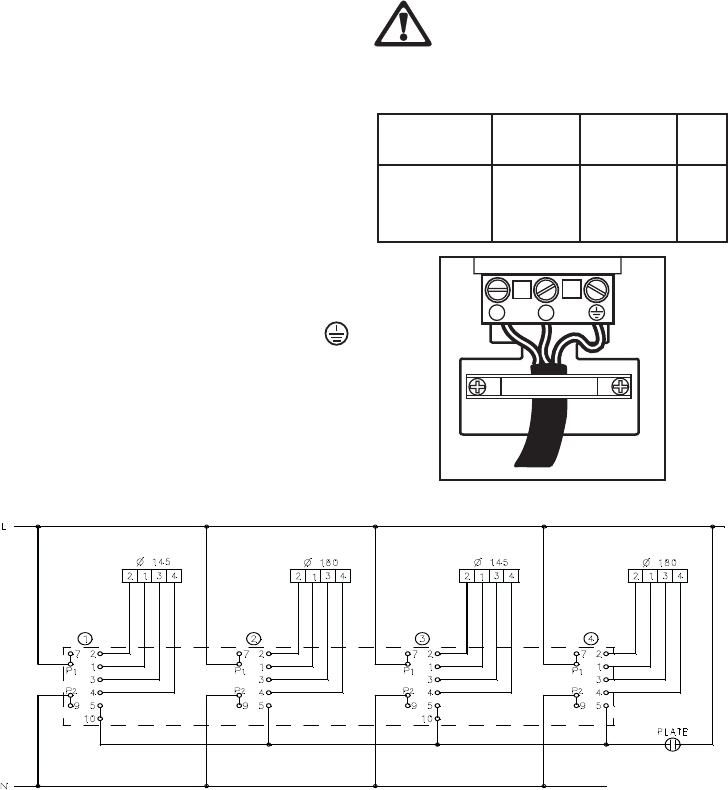
Wiring Diagram
The hob should be connected to a double
pole switch with a minimum gap of 3 mm.
between the switch contacts and of a type
suitable for the required load in compliance
with the current electric regulations. The
switch should be sited within 2m of the hob
and be easily accessible upon completion
of the installation. The switch must not bre-
ak the yellow and green earth cable at any
point.
Ensure that the hob supply cord
does not come into contact with
surfaces with temperatures higher
than 50 deg. C.
)
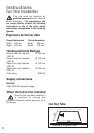
Electrical connections
This hob is designed to be connected to a
230V 50Hz AC electrical supply.
Before switching on, make sure the
electricity supply voltage is the same as that
indicated on the hob rating plate. The rating
plate is located on the bottom of the hob. A
copy is attached on the back cover of this
book.
The hob is supplied without supply cord. A 3
core flexible supply cord must be fitted, in
accordance with the specification given in the
relevant tables.
1) Remove the mains terminal cover
plate from the underside of the hob, to
expose the mains terminal block.
2) Loosen the two cable clamp screws and
lift the top section of the clamp enough to
allow the cable to be passed through.
3) Connect the red (live) wire to the terminal
which is marked with the letter "L".
4) Connect the black (neutral) wire to the
terminal which is marked with the letter "N".
5) After fitting a green or yellow/green sleeve
over the bare copper wire (earth wire),
connect the exposed end to the terminal
which is marked with the earth symbol
or with the letter "E"coloured green and
yellow.
NOTE:
The earth wire should be about 2 cm.
longer than the live and neutral wires.
6) Secure the cable by means of the clamp
screws and refit the terminal block cover.
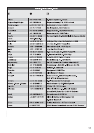
Supply Cable Specifications
Connection Min. size Cable / flex Fuse
via Cable/flex type
Cooker 6 mm
2
PVC/PVC
30 A
Control twin and
Circuit earth
FO 0306