


16 58D6002
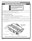
Label all wires prior to
disconnection when
servicing controls.
Wiring errors can cause
improper and dangerous
operation. Verify proper
operation after servicing.
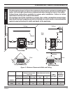
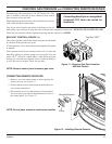
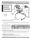
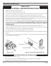
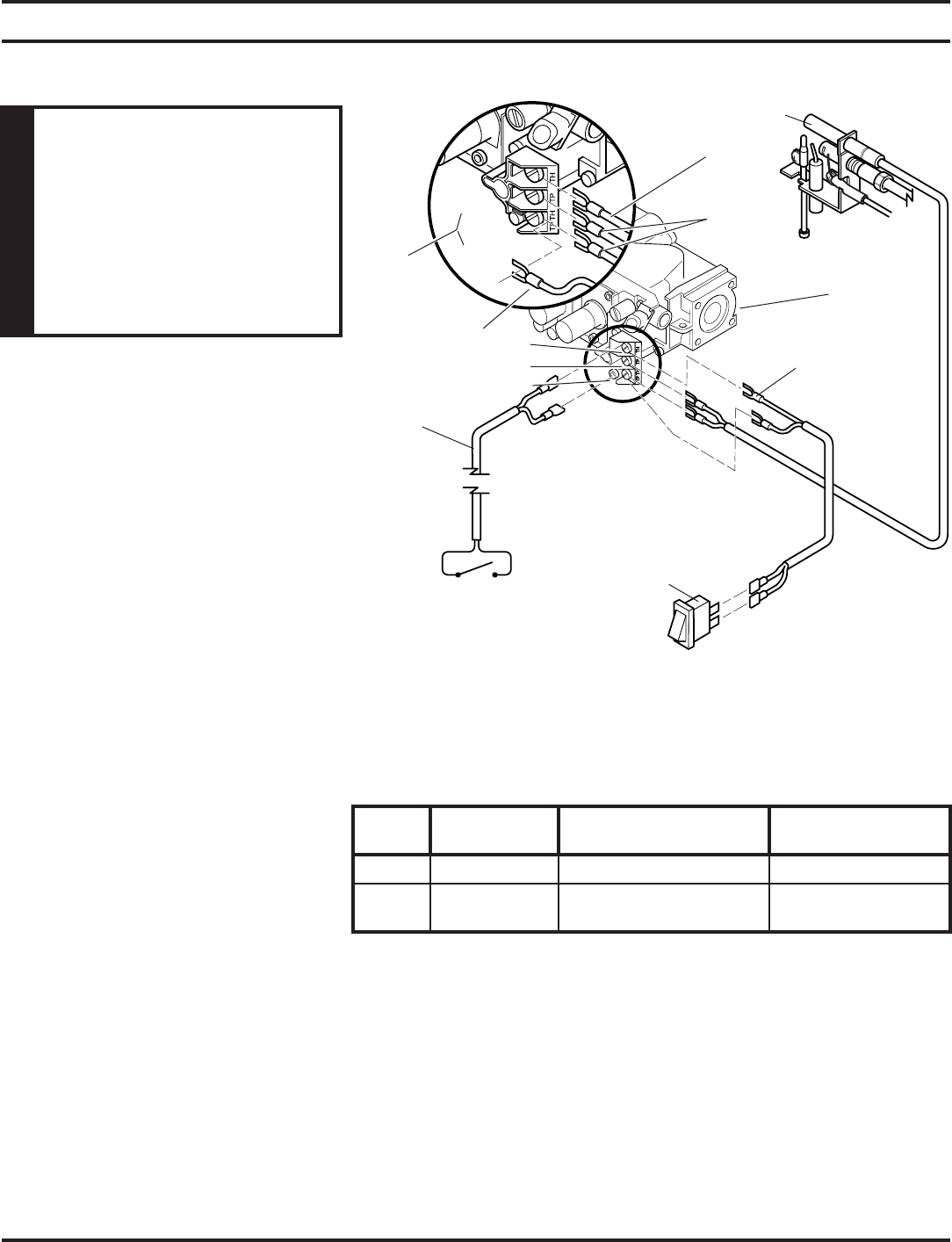
ELECTRICAL WIRING (MILLI-VOLT)
Themilli-voltvalveisaself-poweredcombinationgascontrolTHAT DOES NOT REQUIRE 110 VAC TO OPERATE.
On/Off
Switch
On/Off
Switch
ODS
Pilot
Wall
Switch
Optional Wall
Switch or
Remote
ODS Pilot
Millivolt
Valve
Spade Terminal
3
1
2
CONNECTION
1 = TP
2 = TP, TH
3 = TH
Figure 13 - Wiring Diagram
CONNECTING OPTIONAL WALL SWITCH
1. Use18awg,two-wirecable,15feetmaximumlength.
2. Atoneendofthecable,connectbothwirestothewallswitch.Attheotherend,connectonewiretoTP/THandone
wiretoTH,orconnectthewallswitchtothetwomale(0.25")terminalsontheleftsideoftheunit.Thecolorofthe
wires does not matter.
A. COMPLETE MILLIVOLT SYSTEM CHECK
("A" Reading - On/Off switch contacts CLOSED - Control Knob “ON” - Main Burners should turn ON)
a. Ifthereadingismorethan175millivoltsandtheautomaticvalvestilldoesnotcomeon-replacethevalve.
b. Iftheclosedcircuitreading("A"reading)islessthan175millivolts,determinecauseforlowreading-proceedas
follows:
B. THERMOPILE OUTPUT READING CHECK
(“B” Reading - On/Off switch contacts OPEN - Main burner OFF)
Checkgaspressuretotheunit.Ifgaspressureiswithinminimumandmaximumondataplate,thenreplacepilot.Ifthe
minimummillivoltreadingisnotobtainable,replacepilot.
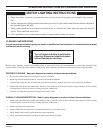
CHECKING SYSTEM OPERATION
The millivolt system and individual compo-
nentsmaybecheckedwithamillivoltmeter
having a 0-1000mv range. Conduct each
checkshowninchartbyconnectingmeter
test leads to terminals as indicated.
Switch
CHECK
TEST
TO TEST CONNECT METER
LEADS TO TERMINALS
METER READING
SHOULD BE
A COMPLETE 2 & 3 SYSTEM MINIMUM 175mv
B THERMOPILE
OUTPUT
1 & 2 SYSTEM 500mv OR MORE