2
Installation
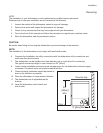
Electrical Connections
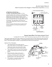
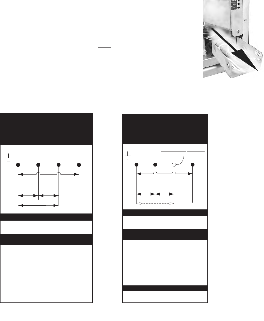
For Model 201HT, 401HT, and 501HT machines beginning with S/N 14236 and above
L1 L2 L3 N
208-230
VAC
208-230
VAC
208-230 VAC
115VAC
GRD
(For machines
beginning with S/N 14236 and above)
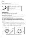
THREE PHASE POWER CONNECTION
Model 201HT, 401HT, 501HT
HOW TO CONNECT 3 PHASE POWER
1. Check the data plate on the front of the
dishwasher for the phase of the machine.
.
2. Remove the lower access panel.
3. Pull power connection box forward and out.
4. The Main Terminal Block has terminals for
L1, L2, L3, Neutral and Ground.
5. Connect ground, then connect
L1, L2, L3 to 208-230VAC.
6. Connect a current carrying neutral to N.
7. Main power connections are complete.
If the data plate says the machine is 3 Phase,
then connect a 3 PH power supply.
/ / / 1
9$&
9$&
9$&
9$&
*5'
)RUPDFKLQHV
EHJLQQLQJZLWK61DQGDERYH
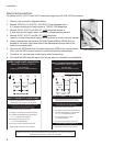
6,1*/(3+$6(32:(5&211(&7,21
0RGHO+7+7+7
'RQRWFRQQHFWSRZHUWR/
+2:72&211(&73+$6(32:(5
&KHFNWKHGDWDSODWHRQWKHIURQWRIWKH
GLVKZDVKHUIRUWKHSKDVHRIWKHPDFKLQH
5HPRYHWKHORZHUDFFHVVSDQHO
3XOOSRZHUFRQQHFWLRQER[IRUZDUGDQGRXW
7KH0DLQ7HUPLQDO%ORFNKDVFRQQHFWLRQV
IRU///1HXWUDODQG*URXQG
&RQQHFWJURXQGWKHQFRQQHFW
//WR9$&
&RQQHFWDFXUUHQWFDUU\LQJQHXWUDOWR1
0DLQ3RZHUFRQQHFWLRQVDUHFRPSOHWH
,IWKHGDWDSODWHVD\VWKHPDFKLQHLV3KDVH
WKHQFRQQHFWD3+SRZHUVXSSO\
'2127&211(&732:(572/
ATTENTION
Models 201HTN, 201LT, 401HTN, 501HTN, 501LT are equipped with a 4 ft. power cord and plug.
These models only require a 115VAC,15A receptacle.
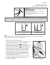
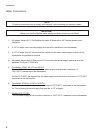
1. Refer to the connection diagrams below.
2. Models 201HTN /LT, 401HTN, 501HTN /LT are equipped with a
4 ft. power cord/plug and only require a 115VAC,15A receptacle.
3. Models 201HT, 401HT, and 501HT 1 PH machines require a
3-wire plus ground supply which includes a current carrying neutral.
4. Models 201HT, 401HT, and 501HT 3 PH machines
require a 4-wire plus ground supply which includes a current carrying neutral.
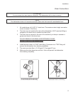
5. Power connections are made at the Main Terminal Block (MTB) which is
located at the lower right-hand side of the dishwasher directly behind the
lower front access panel.
6. Remove the MTB cover and 2 screws holding the MTB to the machine base.
Then, pull the MTB up and forward to make the electrical connections.
7. Provide a 3 ft. service loop in the supply cable for servicing.
8. Re-install the MTB and the lower front access panel to complete the installation.
Pull the MTB out to wire
main incoming power.


