


67
All Models - Timer Board Troubleshooting
Test/Condition Indication/Cause Recomendation/Solution
1. Run LED is lit
Board has power
Machine is powered up and Run LED Possible bad start switch, scrub switch Unplug low voltage plug. If Run LED lights up:
is not lit or wiring short (does not apply to S.S. The start switch or scrub switch failed in the closed
Pizio switch on model 501 or UH200) position, or there is a wiring short
Machine is powered up and Run LED Check voltage
is not lit after unplugging the low
voltage plug
2. Wash pump runs but nothing else works
4 amp board output fuse is blown Replace the 4 amp fuse. Check for wiring problem
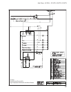
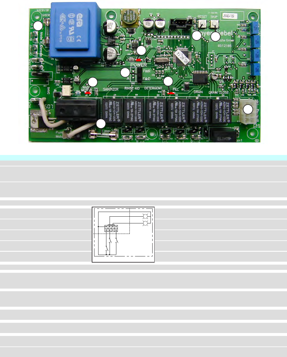
3. Check continuity of the start switch
Use plug pin #8, wire #15 as common to plug pin # 1,
wire #20 (see Fig.1)
Check continuity of the scrub switch Use plug pin #8, wire #15 as common to plug pin # 3,
wire #19 (see Fig.1)
Check continuity of the cycle light Use a meter with diode setting - to cycle light, plug
pin # 6, wire #16 and common pin # 8, wire # 15
Check continuity of the scrub light Use a meter with diode setting - to scrub light, plug
pin # 7, wire #17 and common pin # 8, wire # 15
Check continuity of door safety switch Use a meter with diode setting - to door safety switch,
plug pin # 4, wire #18 and common pin # 8, wire # 15
4. Fill LED is lit
Indicates output voltage to fill valve
5. Select the appropriate setting on the
Note: This solid state timer board is used for
Set dipswitch to FWR for model UH170 and UH200
dipswitch for the model of machine
several different models Set dipswitch to F&D for model 201, 401, 501, UH100
the solid state timer will be installed in
6. Use the skip switch to force the timer
Eg: Pressing the skip switch immediately after starting
to the next segment of the cycle the cycle will make the machine skip the wash cycle,
and go straight into the drain cycle
7. Use the reset button to reset the solid
The reset button will reboot the solid state timer
state timer board board (much like rebooting your computer)
8. 0.063 amp internal board supply fuse
Replace the solid state timer board
is blown
9. Wash motor LED is lit
Indicates output voltage to the wash motor during
wash/rinse cycle only.
LED is not lit during soft start
Wash motor LED is not lit, but wash Replace the board
motor runs continuously
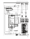
Troubleshooting Guide
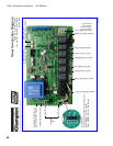
Troubleshooting Timer Board P/N 0712105
June 2010
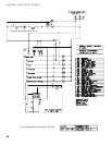
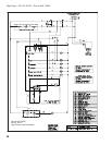
LOW VOLTAGE SECTION
MAXIMUM OVERCURRENT
PROTECTION 40 AMPS
MINIMUM CIRCUIT AMPACITY
40 AMPS
PROTECTION 30 AMPS
MINIMUM CIRCUIT AMPACITY
MAXIMUM OVERCURRENT
30 AMPS
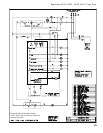
2 AND 5 VDC
EWL
DVC
DIAGRAM STATE
END OF CYCLE
POWER-OFF
DOOR-OPEN
WP
DP
RAP
DEP
FRV
DVO
CPS
BFS
SS
EWS
DSS
CL
POL
1
2
COMMON
0512092 REV 3
208/230 VAC
NUMBER/REV
BOOSTER HEAT
1HTR
BT
BS
26-FEB-07
DATE
HC1
PER LOCAL ELECTRICAL CODES
PS
HC1
GND
TO CUSTOMERS DISCONNECT SWITCH
115-208/230V 60HZ
TT
TS
WHTR
DP
DRAIN PUMP
CB
CIRCUIT BOARD
DVO
DRAIN VALVE OPEN
BFS
BOOSTER FILL SWITCH
FILL/RINSE VALVE
GROUND
DOOR SAFETY SWITCH
DRAIN VALVE CLOSED
GND
DVC
FRV
DSS
CYCLE LIGHT
WASH PUMP
CHEMICAL PRIME SWITCH
START SWITCH
BOOSTER CONTACTOR
BOOSTER HEATER
DETERGENT PUMP
POWER ON LIGHT
W
P
SS
CPS
CL
1HTR
POL
HC1
DEP
BOOSTER SAFETY THERMOSTAT
EXTENDED WASH SWITCH
SANITIZER PUMP
SP
EWS
BS
POWER ON SWITCH
RINSE AID PUMP
TANK HEAT SAFETY THERMOSTAT
TANK HEAT THERMOSTAT
BOOSTER THERMOSTAT
TT
TS
BT
RAP
PS
EXTENDED WASH LIGHT
WASH TANK HEATER
WHTR
EWL
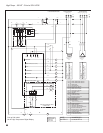
5 kW
HIGH TEMP DIGITAL UNDERCOUNTER
RTS
WTS
RINSE TEMPERTURE SENSOR
WASH TEMPERTURE SENSOR
WTS
RTS
GND
HC1
5 kW
BOOSTER HEAT
208/230 VAC
1HTR
208/230V+115V NEUTRAL 60
HZ
21
NL2L1
DETERGENT
FILL/RINSE
DRAIN VALVE CLOSED
DRAIN VALVE OPEN
DRAIN PUMP (not on 501HT)
WASH PUMP
R/A
NEUTRAL
115 V
ON/OFF
BOOSTER
1L2
1L1
1
5
1
3
4
1L1
7
8
9
N
22
15
17
16
18
19 20
15
10
1
N
1
1H2
1H1
11
12
8
9
7
13
14
10
CB
8 7 56
4 3 2 1
4 3 2 1
115 V
NEUTRAL
30
31
32
33
L1 L2 NL3
1H1
1H3
1H2
SINGLE PHASE THREE PHASE
L2
L1
10
Fig. 1
3
1
2
4
5
7
6
9
8