15
W415-0158 / E / 02.19.04
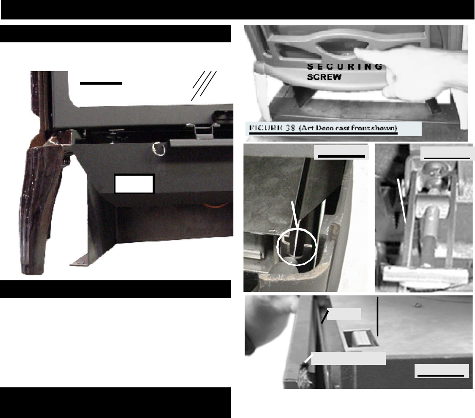
1. Lift the top casting off the unit.
2. Fit the securing bolts on the cast front into each of the
respective retainer brackets (located at either side on the
top SEE FIGURE 37b). Insert and tighten the securing screw
from the bottom up (located at the lower center behind the
cast front SEE FIGURE 37a). This will hold the cast front in
place. Replace the top casting.
3. To remove the front, repeat in reverse order.
When installing the glass door, a simple procedure must
be followed in order to not damage the door.
1. Lift the top casting off.
2. Undo the securing screw (located at the lower center of
the cast front) holding the cast front in place. Figure 37a.
3. Lift the cast front out of its retainers (located at either
side on the top). Figure 37b.
4. Open the valve control cover. Pull the latch handles forward
to release. Figure 37c. The door may now be safely removed
by swinging the bottom out and lifting it off. To install the door,
repeat in reverse order.
The return flange must fit over the top of the ridge
so that it rests on top of the firebox. Figure 37d.
The 'T' latch portion is threaded and can be loos-
ened or tightened to adjust for an effective door seal.
Care must be taken when re-installing the door to
ensure that the gasket at the top of the door does
not bunch.
Remove the backing of the logo supplied and centre over
the logo installation holes, as indicated.
LOGO
RIDGE
RETURN FLANGE
FIGURE 38d
TOP
FRONT
RETAINER
FIGURE 38b
FIGURE 38c
'T' LATCH
HANDLE
FINISHING
LOGO PLACEMENT
FRONT CAST INSTALLATION
GLASS DOOR INSTALLATION
AND REMOVAL
FIGURE 37
