MAINTENANCE
Seasonal maintenance
WEEKLY - DESCALE
Push and pull the de-scaling lever in and out as well as turning
slightly at the same time completely two or three times. Push in for
normal burner operations or before relighting.
EVERY 3 TO 4 MONTHS - CLEAN BURNER
Remove all three catalyser components (C, D, E, figure 15,
page 10). Remove any carbon residue and remaining oil from the
burner using a slightly damp cloth. Buff dry before reinstalling.
EVERY 3 TO 4 MONTHS : CHIMNEY INSPECTION
The chimney and the chimney connector must be inspected at least
once every 3 months during the heating season to ascertain
whether there has been a buildup of soot in the system. If a soot
buildup has occurred, it should be removed to reduce the risk of
chimney fires.
ONCE OR TWICE A YEAR : FLUE BAFFLES INSPECTION
- Remove the flue baffle (page 12). If a soot buildup has occurred
on the flue baffles and the combustion chamber, it should be
removed.
YEARLY : CHIMNEY MAINTENANCE
The chimney is to be swept at least once a year. It is also
recommended that prior to every heating season the entire system
be professionally inspected, cleaned and repaired where
necessary.
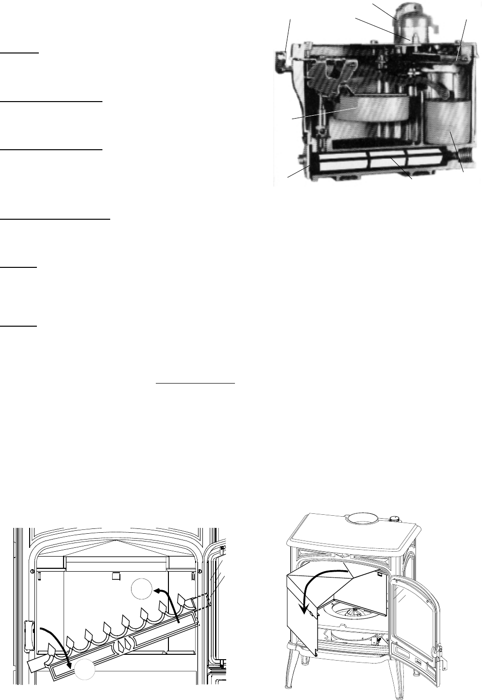
YEARLY - CLEAN CARBURETOR FILTER
1
. Set the control knob to “0".
2.
Turn off oil supply at the valve or the tank valve.
3.
Raise the safety lever (D).
4.
Place a container under the carburetor to contain any spillage. Remove the filter plug held on with two screws.
5.
Pull out the filter (E) and clean in oil using a soft brush. Never use a wire brush.
6.
Replace filter and plug.
Clean all enamelled stove panels and the outside of the glass using a slightly dampened cloth. NEVER CLEAN WHEN
THE STOVE IS HOT.
DOOR GASKET REPLACEMENT
Check the door gasket periodically to ensure the seal is functioning properly and the door fits tight. Replace the gasket if
necessary.
Removingthefluebaffle
B
C
D
F
H
G
E
A
Figure 19
1
2
A :Controlknob
B : Thermostat control
C : Oil level regulator
D : Safety lever
E :Filter
F : Main float
G : Safety float
H : Filter cavity
Figure 20
Figure 21
Document n° 1043-1 ~ 15/01/2002
12


