


5
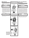
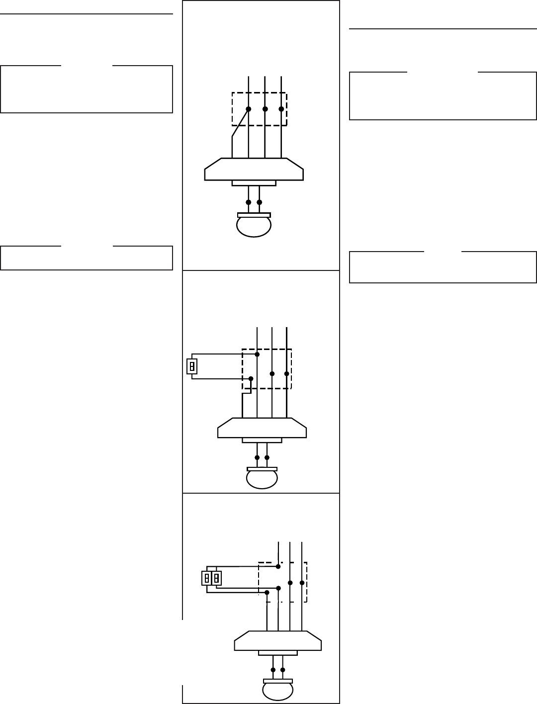
FAN CONTROLLED BY PULL CHAIN SWITCH.
LIGHT CONTROLLED BY PULL CHAIN SWITCH.
VENTILADOR CONTROLADO POR INTERRUPTOR
A CADENILLA DE TIRO. LUZ CONTROLADA POR
INTERRUPTOR A CADENILLA DE TIRO.
CEILING BOX
CAJA DE TECHO
LINE
LINEA
FAN
VENTILADOR
LIGHT
LUZ
WHITE - BLANCO
WHITE - BLANCO
BLUE OR RED
AZUL O ROJO
BLACK - NEGRO
BLUE OR RED
AZUL O ROJO
BLACK
NEGRO
WHITE
BLANCO
GROUND
TIERRA
BLACK
NEGRO
WHITE
BLANCO
GROUND
TIERRA
Do not connect RED or BLUE if light is not installed.
Wire nut end of RED or BLUE wire.
No conecte el ROJO o AZUL si no ha instalado la luz.
El conector va al final del alambre ROJO o AZUL.
FIG. 11
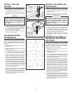
FAN CONTROLLED BY PULL CHAIN SWITCH.
LIGHT CONTROLLED BY WALL SWITCH.
VENTILADOR CONTROLADO POR INTERRUPTOR
A CADENA DE TIRO. LUZ CONTROLADA POR
INTERRUPTOR DE PARED.
CEILING BOX
CAJA DE TECHO
LINE
LINEA
FAN
VENTILADOR
LIGHT
LUZ
WHITE - BLANCO
WHITE - BLANCO
BLUE OR RED
AZUL O ROJO
BLACK - NEGRO
BLUE OR RED
AZUL O ROJO
BLACK
NEGRO
WHITE
BLANCO
GROUND
TIERRA
BLACK
NEGRO
WHITE
BLANCO
GROUND
TIERRA
LIGHT
SWITCH
INTERRUPTOR
DE LUZ
CEILING
BOX
CAJA
DE TECHO
LINE
LINEA
FAN
VENTILADOR
LIGHT
LUZ
WHITE - BLANCO
WHITE - BLANCO
BLUE OR RED
AZUL O ROJO
BLACK - NEGRO
WHITE-BLANCO
GROUND-TIERRA
BLACK-NEGRO
BLUE OR RED
AZUL O ROJO
LIGHT
LUZ
FAN
VENTILADOR
BLACK-NEGRO
WHITE-BLANCO
GROUND-TIERRA
FAN AND LIGHT CONTROLLED BY INDEPENDENT
WALL SWITCHES.
VENTILADOR Y LUZ CONTROLADOS POR
INTERRUPTORES DE PARED INDEPENDIENTES.
NOTE: If variable speed fan opera-
tion is desired - use only Broan
Models 78V, 78W, 79V, or 79W.
NOTA: Si se desea un ventilador
de velocidad variable - use
solamente los Modelos Broan 78V,
78W, 79V, o 79W.
WIRE THE FAN
1. Use the plastic bag that the fan motor was
packaged in to cover up the top of the motor to
prevent small parts from falling into the motor
housing.
WARNING
TURN OFF ELECTIC POWER AT SERVICE
ENTRANCE BEFORE MAKING ELECTRI-
CAL CONNECTIONS OR INSTALLING A
LIGHT KIT.
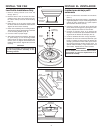
2. Make electrical connections. (FIG. 11) Wire
black to black, white to white, and green to
house ground using proper connections. FAN
MUST BE GROUNDED. All splices and wires
should be pushed back into ceiling box so they
will not be pinched or cut by canopy. After mak-
ing the wire connections, the wires should be
spread apart with the grounded conductor
(white) and the equipment-grounding conduc-
tor (green) on one side of the ceiling box and
the ungrounded conductors on the other side
of the ceiling box.
NOTE
Red or Blue wire is for optional light kit.
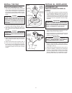
3. Fasten canopy to fan mounting bracket with
four screws. (FIG. 10) Remove the plastic
bag from around the fan.
HAGA LAS CONEXIONES
ELECTRICAS
1. Use la bolsa de plástico en que vino el motor para
cubrir la parte superior del motor a fin de evitar que
las piezas pequeñas caigan dentro.
ADVERTENCIA
CORTE LA CORRIENTE ELECTRICA EN EL
SERVICIO DE ENTRADA ANTES DE HACER
LAS CONEXIONES ELECTRICAS O INSTALAR
LAS LUCES.
2. Haga las conexiones eléctricas. (FIG. 11) Con-
ductor negro a conductor negro, blanco a blanco,
y verde a tierra de la casa empleando las
conexiones correctas. EL VENTILADOR DEBE
CONECTARSE A TIERRA. Todos los empalmes y
conductores deberán empujarse dentro de la caja
de techo para que la cúpola no los pinche o corte.
Después de hacer las conexiones, los alambres
deberán separarse poniendo en un lado de la caja
de techo el conductor a tierra (blanco) y el con-
ductor a tierra del equipo (verde) y en el otro lado
de la caja los conductores sin conexión a tierra.
NOTA
El conductor rojo o azul es para el juego de
luces opcionales.
3. Asegure la cúpola a la ménsula de montaje del
ventilador con cuatro tornillos. (FIG. 10) Quite la
bolsa de plástico de alrededor del ventilador.